


ADXL180
Rev. 0 | Page 11 of 56
SIGNAL PROCESSING
The ADXL180 contains an on-board set of signal processing
blocks both prior to and after ADC conversion. The first stage is
a fully differential, switched capacitor, low-pass, three-pole
Bessel filter. Range scaling is also handled in one of the filter
blocks, enabling 50
g
to 500
g
range capability. At this point, an
analog output test signal (V
SCO
) is available to the user in a
diagnostic mode. The signal then converts by a 10-bit rail-to-rail
SAR ADC. In the digital section, an auto-zero routine is
available to the user as part of the state machine in addition to
error detection features such as offset drift detection.
DIGITAL COMMUNICATIONS STATE MACHINE
The ADXL180 digital state machine is based on a Core 5 phase
state machine implemented in high density CMOS. This state
machine handles the sequential states of
Phase 1.
Initialization.
Phase 2.
Device data transmission, including individual serial
number and user-programmed data.
Phase 3.
Self-diagnostic, including automatic full electro-
mechanical self-test with internal error detection
available.
Phase 4.
Auto-zero initialization, if selected. During this phase,
acceleration data is already available.
Phase 5.
Normal acceleration data transmission.
2-WIRE CURRENT MODULATED INTERFACE
The data that is generated during these five phases is trans-
mitted using a 2-wire high voltage communication port. This
allows the device to be powered by a fixed supply voltage, and
communicate back to the system or ECU electronics by modulating
current. Current modulated messages are encoded using Man-
chester encoding.
SYNCHRONOUS OPERATION AND DUAL DEVICE
BUS
In a point-to-point bus topology, the ADXL180 supports asyn-
chronous transmission of data to the receive device every 228 μs,
controlled by the on-board state machine. A synchronous option
is also available, allowing two devices to be on the same bus
using time division multiplexing where each device transmits its
data during a known time slot.
Synchronization is achieved by voltage modulated synchronization
pulses, configuring the ADXL180 device into a synchronous
mode, and establishing data frame time slots. The high voltage
communication port registers valid synchronization pulses and
enables message-by-message advancement of the state machine
rather than asynchronous timed regular data transmission.
PROGRAMMED MEMORY AND CONFIGURABILITY
Factory-Programmed Serial Number and Manufacturer
Information
The ADXL180 includes a 32-bit factory-programmed serial
number, as shown in Table 5. This serial number transmits
during Phase 2 of startup for all devices to enable robust quality
tracking of individual devices, and it is field readable. In addition,
this data includes revision information and manufacturer identi-
fication in case multiple devices used within a single application
are from different manufacturers or generations of parts.
User-Programmable Data Register
The ADXL180 gives the user an 8-bit register of user-program-
mable data, which is transmitted during Phase 2 of the state
machine. In addition, the UD8 bit, a ninth user-available bit,
is transmitted separately during Phase 2 and can be used for
various purposes, such as orientation definition or module type.
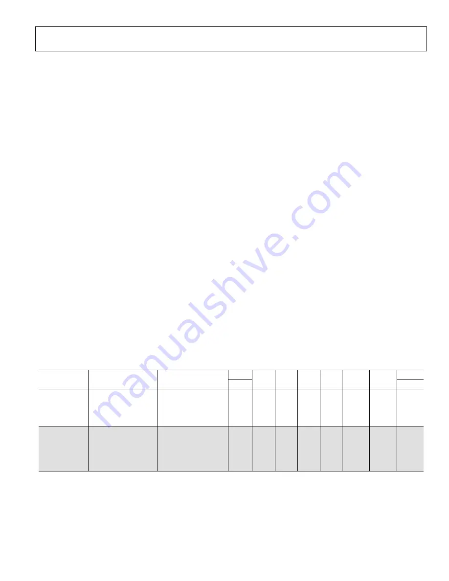
Table 5. Factory Programmed and User-Programmed Memory
Programmed By
Configuration Mode
Register Address
Configuration Mode
Register Name
MSB
D6 D5 D4 D3 D2 D1
LSB
D7 D0
User
0000b
UREG
UD7 UD6 UD5 UD4 UD3 UD2 UD1 UD0
0001b
CREG0
UD8 BDE MD1 MD0 FDLY DLY2 DLY1 DLY0
0010b CREG1 STI
AZE
SYEN
ADME
ERC
SVD
DAT
MAN
0011b CREG2 CUPRG CUPAR SCOE
FC1
FC0
RG2
RG1
RG0
Factory
1011b
SN0
SNB7
SNB6
SNB5
SNB4
SNB3
SNB2
SNB1
SNB0
1100b
SN1
SNB15 SNB14 SNB13 SNB12 SNB11 SNB10
SNB9
SNB8
1101b
SN2
SNB23 SNB22 SNB21 SNB20 SNB19 SNB18
SNB17
SNB16
1110b
SN3
SNB31 SNB30 SNB29 SNB28 SNB27 SNB26
SNB25
SNB24
1111b
MFGID
SNPRG SNPAR REV2
REV1
REV0
MFGID2 MFGID1 MFGID0


