background image

ADMV8818-EVALZ

 Evaluation Board User Guide 

UG-1921 


Rev. 0 | Page 9 of 18 

PERFORMING THE EVALUATION 

ADMV8818-EVALZ QUICK START 

To set up the ADMV8818-EVALZ, take the following steps: 
1.


Connect the RFIN and RFOUT ports to a network analyzer 
(or a similar instrument). Typically, RFIN and RFOUT are 
connected to Port 1 and Port 2 on the network analyzer, as 
shown in Figure 2. 

2.


Connect th

SDP-S

 to the 120-pin connector on the 

ADMV8818-EVALZ. Do not connect the SDP-S to the PC 
until after completing Step 3 or Step 4. 

3.


On the ADMV8818-EVALZ, slide the S2 switch 
downward (as shown in Figure 2) to power the 
ADMV8818-EVALZ from the 5 V USB supply voltage 
from the PC via the SDP-S. 

4.


Alternatively (to Step 3), slide the S2 switch upward and 
connect power supplies to the VPOS and VNEG ports. 
The applicable voltage range for VPOS is between 3.5 V 
and 5.5 V, and the applicable voltage range for VNEG is 
between −5.5 V and −2.7 V. The external supply current 
limits must be set to 20 mA. Expected supply current draw 
for VPOS is 12 mA to 14 mA and for VNEG is 2 mA to 
3 mA. Th

ADMV8818

 chip current drawn per supply pin 

is typically 10s of microamps or less. Most of the current 
drawn from the ADMV8818-EVALZ comes from the LDO 
regulators and the status indicator light emitting diodes 
(LEDs), DS1 to DS3. 

5.


Connect a USB cable between the PC and the SDP-S. 

6.


Open th

ACE

 software. The 

ADMV8818 Board

 appears 

in the 

Attached Hardware

 section of the 

Start

 tab. Double 

click the 

ADMV8818 Board 

plugin to open two tabs, one 

for the 

ADMV8818 Board

 plugin view and one for the 

ADMV8818

 chip plugin. 

7.


Use the 

CONFIGURATION

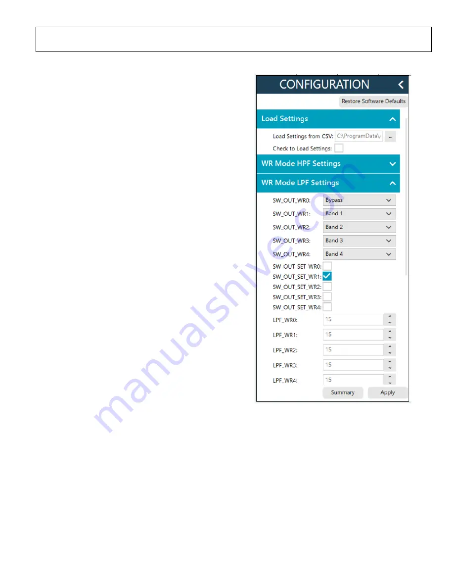
 section (see Figure 9) in the 

ACE software to initialize the chip. By default, the 

ADMV8818_Register_Load_1.csv

 file is loaded into this 

section. Click 

Apply

 to send the default settings to the chip 

and to allow the main diagram user controls to become 
editable. 

NETWORK ANALYZER SETTINGS 

When evaluating the ADMV8818-EVALZ, a good starting 
point for configuring the network analyzer is as follows: 


Start frequency = 0.1 GHz 


Stop frequency = 40 GHz 


Number of points = 400 


Step size = 100 MHz 


Power level = −10 dBm 


Measure types = S-parameters (S21, S11, and S22) 


Format = log magnitude 


Calibration = full 2-port 


25839-

009


Figure 9. ADMV8818 

CONFIGURATION

 Section 

CSV FILES 

By default, the 

ADMV8818_Register_Load_1.csv

 file is loaded 

into the 

CONFIGURATION

 section. To load a different CSV 

file in the 

CONFIGURATION

 section, take the following 

steps: 
1.


If the 

Modify

 button is visible, click to allow changes. 

2.


Click 

Restore Software Defaults

 to zero out the 

CONFIGURATION

 section. 

3.


Click the 

 button next to 

Load Settings from CSV

 to 

select which CSV file to load (see Figure 9)

4.


Select the

 Check to Load Settings

 check box to load the CSV 

file contents into the 

CONFIGURATION

 section. Note that 

a check mark does not appear when the check box is selected. 

5.


Click 

Apply

 to send out the settings to the hardware. 

Summary of Contents for ADMV8818-EVALZ

Page 1: ...orporates the ADMV8818 chip as well as a negative voltage generator low dropout LDO regulators and an interface to the EVAL SDP CS1Z SDP S system demonstration platform SDP to allow simple and efficie...

Page 2: ...ion Board Software 4 Installing the ACE Software ADMV8818 Plugins and Drivers 4 Plugin Overview 5 Plugin Details 6 Performing the Evaluation 9 ADMV8818 EVALZ Quick Start 9 Network Analyzer Settings 9...

Page 3: ...ernatively the ADMV8818 EVALZ can be powered externally by sliding the S2 switch upward and then connecting power supplies to the VPOS and VNEG Subminiature Version A SMA ports or test points The appl...

Page 4: ...he following steps to install the updated ACE software 1 Uninstall the current version of the ACE software on the PC 2 Delete the ACE folder found in C ProgramData Analog Devices and C Program Files x...

Page 5: ...ectively The ADMV8818 chip plugin includes the following feature sections see Table 1 for additional information on these sections The CONFIGURATION section load from CSV The Logic Pins section The SF...

Page 6: ...L settings that are used when the chip is placed into the SPI fast latch mode Note that this function is not shown in Figure 7 Scroll down in the CONFIGURATION section to view this function Lookup Tab...

Page 7: ...the Input Switch position shows WR When displaying an LUT number the Input Switch position reflects the SW_IN_SET_y bit fields where y is a number from 0 to 127 depending on the LUT number selected O...

Page 8: ...Changes does not need clicking to apply or read back the block diagram settings J2 To read back all of the SPI registers of the chip click Read All J3 Click Reset Chip to reset the chip J4 Click Diff...

Page 9: ...Open the ACE software The ADMV8818 Board appears in the Attached Hardware section of the Start tab Double click the ADMV8818 Board plugin to open two tabs one for the ADMV8818 Board plugin view and on...

Page 10: ...ADMV8818 supply current but it must be noted that each supply pin is also connected to status indicator LEDs DS1 to DS3 and each LED draws approximately 2 mA of current Remove the R2 R3 and R90 resist...

Page 11: ...1UF S1 DNI RFIN C14 R11 C3 C13 RFOUT THRU1 THRU2 C1 C2 R80 R1 DS2 DS1 R2 R3 DS3 U7 R12 R13 R14 R15 CSB CSB_U1 SFL 3P3VUSB SFL CSB_AUX SDI 3P3V SCLK CSB_U1 RFOUT THRUCAL RSTB 2P5V N2P5V N2P5V RFIN 3P3...

Page 12: ...4 R53 U6 R52 TWI_A0 3P3VUSB SCL_SDP SDA_SDP 1 2 3 6 5 8 4 7 VSS VCC WP A2 A1 A0 SCL SDA 10UF TBD0402 1UF 1UF 10UF 1UF 10UF ADP7156ACPZ 2 5 0 0 TBD0402 1UF 0 DNI 0 TBD0402 DNI 1UF 0 RED 0 10UF 1UF RED...

Page 13: ...ADMV8818 EVALZ Evaluation Board User Guide UG 1921 Rev 0 Page 13 of 18 25839 012 Figure 12 ADMV8818 EVALZ Layer 1...

Page 14: ...UG 1921 ADMV8818 EVALZ Evaluation Board User Guide Rev 0 Page 14 of 18 25839 013 Figure 13 ADMV8818 EVALZ Layer 2...

Page 15: ...ADMV8818 EVALZ Evaluation Board User Guide UG 1921 Rev 0 Page 15 of 18 25839 014 Figure 14 ADMV8818 EVALZ Layer 3...

Page 16: ...UG 1921 ADMV8818 EVALZ Evaluation Board User Guide Rev 0 Page 16 of 18 25839 015 Figure 15 ADMV8818 EVALZ Layer 4...

Page 17: ...0 R1 to R10 Resistors 330 1 16 W 5 0402 Panasonic ERJ 2GEJ331X 6 R11 to R16 Resistors 33 1 10 W 5 0402 Panasonic ERJ 2GEJ330X 14 R21 to R34 Resistors 0 1 16 W 0402 Stackpole RMCF0402ZT0R00 2 R53 R54 R...

Page 18: ...sfer any portion of the Evaluation Board to any other party for any reason Upon discontinuation of use of the Evaluation Board or termination of this Agreement Customer agrees to promptly return the E...

Reviews: