Evaluation Board User Guide
UG-072
Rev. A | Page 3 of 20
QUICK START SETUP
PREPARING FOR THE FIRST USE
To get started, use the following steps:
1.
Install the SigmaStudio software.
2.
Plug in the USBi.
3.
Power up the board.
4.
Connect the audio cables.
5.
Set the switches and jumpers.
SIGMASTUDIO SOFTWARE INSTALLATION
1.
Download the
SigmaStudio.zip
file from
http://www.analog.com/sigmastudiodownload
and extract
the files to your PC. The key for the download is provided
in the box with the evaluation board.
2.
Install Microsoft® .net Framework V 3.5. If you do not
already have it installed, this can be downloaded from the
Microsoft website.
3.
Install SigmaStudio by double-clicking
setup.exe
and
following the prompts. A computer restart is not required.
POWERING UP THE BOARD
The board is powered from the included 6 V dc power supply
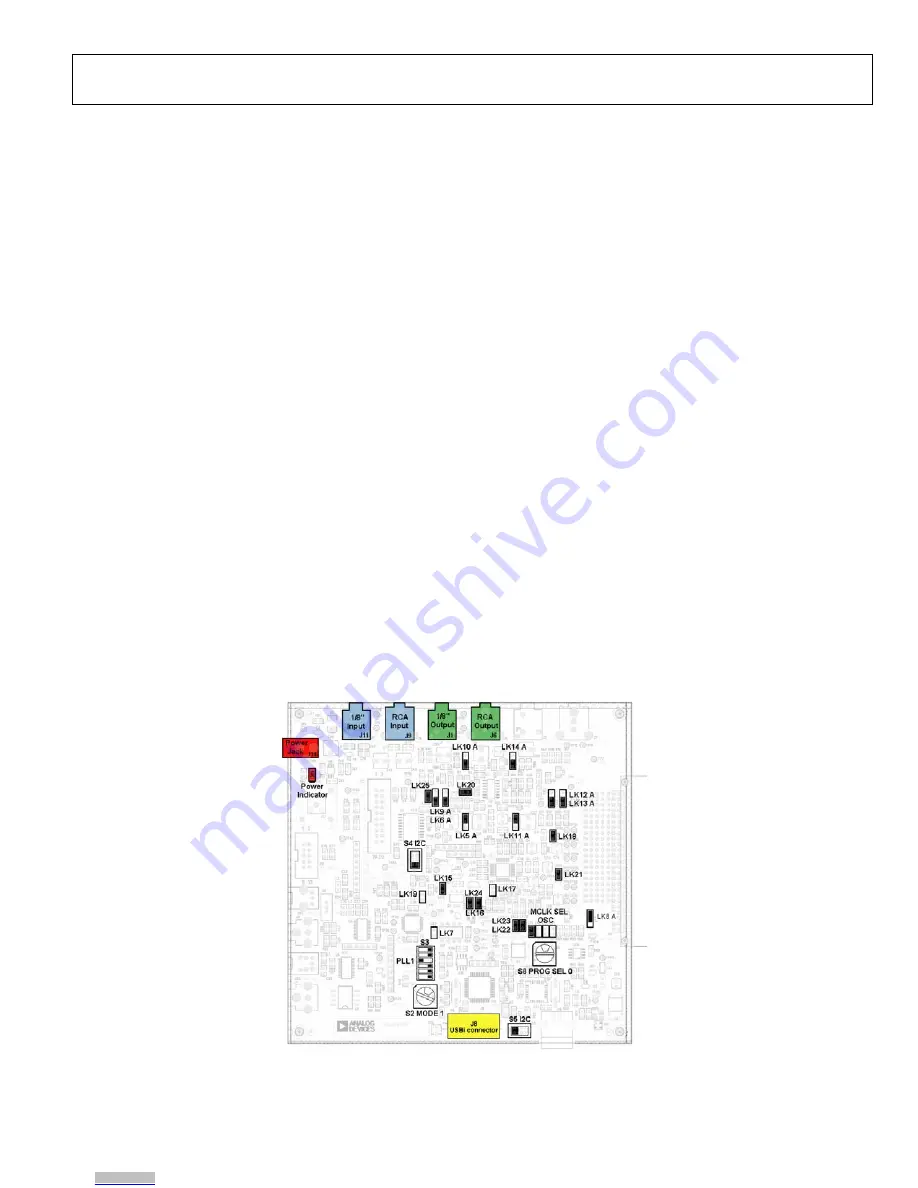
connected to J14. The power indicator LED, D11, should be lit.
HARDWARE SETUP—USBi
1.
Plug in a power supply to the power jack, J14, of the EVAL-
ADAU1401AEBZ evaluation board.
2.
Plug the USBi into the USB port of the PC using the mini-
USB cable.
3.
Plug the USBi into the control port on the evaluation board
(marked yellow in Figure 2).
4.
Connect the USB cable to the computer and to the USBi.
5.
When prompted for drivers, use the following options:
•
Choose
Install from a list or a specific location
.
•
Choose
Search for the best driver in these locations
.
•
Check the box for
Include this location
in the search.
•
The USBi driver is located in
C:\Program Files\
Analog Devices Inc\Sigma Studio\USB
drivers
, click
Next
.
•
If prompted to choose a driver, select
CyUSB.sys
.
•
In XP only, click
Continue Anyway
if a prompt
appears indicating the software has not passed
Windows Logo testing.
6.
Make sure that Switch S4 and Switch S5 of the EVAL-
ADAU1401AEBZ are set to the I2C position.
CONNECTING THE AUDIO CABLES
For this example, set up the board to have stereo analog inputs
and stereo analog outputs. To do so, use the following steps:
1.
Connect the audio source to the IN 0/IN 1 jacks on the top
of the board (marked blue in Figure 2), using 3.5 mm (⅛”)
cables.
2.
Connect the OUT 0/OUT 1 jacks on the top of the board
(marked green in Figure 2) to your speakers or
headphones.
SWITCH AND JUMPER SETTINGS
To configure the board for stereo analog input and output, make
sure the switches and jumpers are set as indicated in Figure 2.
08697-
002
Figure 2. Evaluation Board Setup and Configuration
Downloaded from
Downloaded from
Downloaded from


