QUICK START GUIDE
SDX-414-DX
Solecis 4K HDMI Digital Switcher
Overview
This guide pertains to the SDX-414-DX 4x1 4K HDMI Digital Switcher with DXLink
Output (
FG1010-314
). The purpose of this document is to illustrate how the device
is to be installed and set up in its simplest configuration by a trained technician.
What?s in the Box?
The following items are included with the SDX-414-DX:
• (2) 5-pin Phoenix connectors
• (1) 4-pin Phoenix connector
• (4) rubber feet
Power
Active power requirements:
• Voltage, DC (typical): 12VDC
• Power consumption (max): 18W
Environmental Requirements
The environmental requirements for the SDX-414-DX are as follows:
•
Operating Temperature
: 32° F (0° C) to 104° F (40° C)
•
Storage Temperature
: -22° F (-30° C) to 158° F (70° C)
•
Operating Humidity
: 5% to 85% RH (non-condensing)
•
Storage Humidity
: 0% to 90% RH (non-condensing)
Configuration
Perform the following to prepare the switcher for network communication:
Setting the Configuration DIP Switches
Use the Configuration DIP switch to enable/disable the LAN ports and set network
connectivity. DIP switch settings are read on reboot. Any changes to the DIP
switch settings are not acted upon until after you reboot the device.
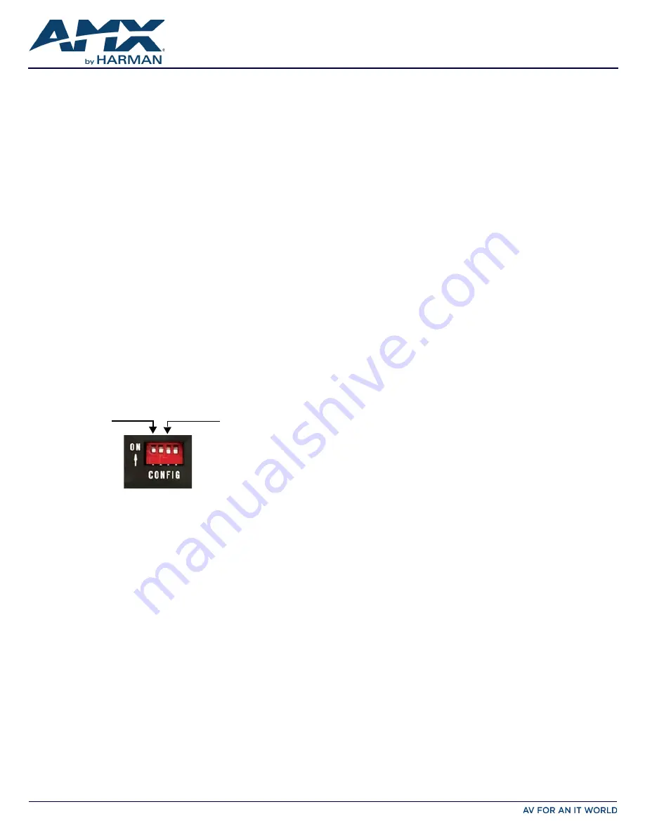
Enabling the LAN 10/100 Ports
The LAN 10/100 ports on the switchers are disabled by default. You can enable
the ports by setting #1 DIP switch to ON (see
FIG. 1
).
Enabling Network Connectivity
Network connectivity on the switchers is disabled by default. You can enable
network connectivity by setting #3 DIP switch to ON (see
FIG. 1
).
FIG. 1
CONFIGURATION DIP SWITCH
Installation
Before connecting the switcher to its peripheral devices and powering the
device, be sure to mount the device using one of the methods detailed below.
You can also pole-mount the switcher using the V Style Single Module Pole
Mounting Kit (
FG1010-723
). The switchers also include rubber feet that you can
apply to the bottom of the device for table-top mounting.
Surface Mounting
The Solecis Digital Switchers can be mounted using V Style Surface Mounting
Brackets (
FG1010-722
). The Surface Mount Brackets are designed for mounting a
single module (to a wall, on or under a desk, etc.) The brackets may be attached
to mount the top or the bottom flush with the mounting surface.
Rack Mounting
You can mount the switcher on a rack shelf by using an NMX-VRK V-Style Rack
Shelf (
FG3201-60
). In addition to the switcher, you can also use wire ties to mount
the switcher’s power supply on the rack shelf.
Consult the Installation Guide included with the mounting hardware of your
choice for mounting instructions.
Getting Connected
The following sections describe how to connect your switcher to your network,
audio/video sources, and accessories.
Connecting the Switcher to a Video Input
The HDMI INPUT connectors on the rear panel route digital video (and audio)
from connected source input devices to the connected output devices. The
SDX-414-DX features four HDMI INPUT connectors.
Connecting the Switcher to a Video Output
The switchers can transmit a signal simultaneously to both DXLink and HDMI
outputs.
• The switcher uses standard HDMI cabling to connect to the HDMI inputs and
outputs. Use an HDMI cable to connect the HDMI OUT port on the rear
panel of the switcher to the display device.
• The switcher uses category cabling to connect to the DXLink output. See
the
Important Twisted Pair Cabling Requirements and Recommendations
section for information about cable requirements for the DXLink port. Use
category cabling to connect the DXLINK port on the rear panel of the
switcher to the DXLink input port on a DXLink receiver, Enova DVX switcher,
or Enova DGX switcher.
Video Switching
Auto Switching mode is the default switching mode. With Auto Switching mode,
the switcher responds to the most recently added video input by switching the
new input to display on the HDMI and DXLink output. If the currently selected
video source is removed, the switcher remains on that input.
You can disable Auto Switching mode by using the VIDIN_AUTO_SELECT NetLinx
command. See the
Solecis SDX Digital Switchers Instruction Manual
for more
information on this command.
To switch between video inputs that have already been established, you can
perform one of the following:
• Use the Select button on the front of the panel to cycle through the video
inputs.
• Use a connected external button (not included) with either of the External
Button/LED Control connectors located on the rear panel of the switcher.
The External Button/LED Control connectors are 5-pin, 3.5mm terminal screw
connectors to which you can connect up to two single-button modules,
such as the HPX-U100-BTN. With a single button module connected to one
of these ports, you can press the button on the module to switch the input
and send a button press event to a connected Master. You can use this
function to have the Master send a command back to the switcher to
execute an additional event.
• Use the NetLinx command CI<input>O<output> to switch between video
inputs. See the
Solecis SDX Digital Switchers Instruction Manual
for more
information on this command.
Toggling Between DHCP and Static IP Addresses
Solecis Digital Switchers support both DHCP and static IP addresses. When the #3
DIP switch is set to ON, the switchers automatically use DHCP with link-local
fallback. However, you can use a static IP address which you can set via a Telnet
command (SET IP), or you can use the factory default static IP address. The
default static IP address can be recalled at any time by resetting the unit to its
factory default configuration. The default link-local address is 169.254.2.2. The
switcher defaults to the link-local address if no IP address is obtained from a DHCP
server.
The ID Pushbutton can be used to toggle between the DHCP and Static IP
Modes.
Perform these steps to toggle between IP addressing modes:
1.
After the switcher boots, press and hold the ID Pushbutton until the STATUS
and LINK/ACT LEDs toggle back and forth in unison approximately 10 times.
2.
Release the pushbutton when the LEDs start to blink faster.
• When you release the Pushbutton, the switcher toggles either from static to
dynamic (DHCP) IP addressing or vice versa and remains in that mode until
you use the ID Pushbutton to toggle the IP mode again or you perform a
factory reset.
• The switcher automatically reboots to complete the process.
Assigning a Device Address (ID Mode)
You can use the ID Pushbutton in conjunction with the ID (Identify) Mode feature
in NetLinx Studio. A momentary press of the ID Pushbutton assigns a device
address to the switcher (which must be bound to the Master). You must first place
the device in ID Mode in NetLinx Studio or the momentary press will be ignored.
NOTE: The latest version of NetLinx Studio is available to download and install from
www.amx.com. Refer to the NetLinx Studio online help for instructions on using
the application.
Perform these steps to assign a device address:
1.
Check to be sure DIP switch #3 on the switcher is set to ON.
2.
In NetLinx Studio’s OnLine Tree, select the Master to which the switcher is
bound.
3.
From the Diagnostic menu, select
Device Addressing
. The Device
Addressing dialog box opens.
4.
In the ID Mode section, enter the Device and System numbers that you
want assigned to the device in the appropriate text boxes.
5.
Click
Start Identify Mode
to place the named system in ID Mode. The button
changes to “Cancel Identify Mode” (click to cancel ID Mode). The text box
below the button displays a “Waiting...Press Cancel to Quit” message.
#1 switch, set to ON
to enable
LAN 10/100 ports
#3 switch, set to ON
to enable network
connectivity