

For full warranty information, refer to the AMX Instruction Manual(s) associated with your Product(s).
6/08
©2008 AMX. All rights reserved. AMX and the AMX logo are registered trademarks of AMX.
AMX reserves the right to alter specifications without notice at any time.
3000 RESEARCH DRIVE, RICHARDSON, TX 75082 • 800.222.0193 • fax 469.624.7153 • technical support 800.932.6993 • www.amx.com
93-0630-10
REV: C
Unpacking the NXP-PLV
1.
Inspect and confirm the contents of the shipment box to verify you have
all specified parts.
2.
Carefully remove the device from the shipping box.
3.
Carefully peel the protective plastic cover from the LCD touchscreen.
NOTE
: If the protective plastic LCD cover is not removed, the device may not
respond properly to touch points on the screen or allow proper screen
calibration.
Connecting the NXP-PLV
The NXP-PLV is intended to stand alone on a desktop or tabletop without a
bracket or support platform, but it still needs to communicate with its associated
cameras in order to function. This may be done by connecting it to a NetLinx
master or via a hub or router, but the device still needs to be powered up and
connected before it is fully functional.
1.
Make sure that all data and power wiring connectors are connected to
their respective terminal locations on either the Breakout Box, Ethernet
port, or NetLinx Master.
2.
Connect all data and power wiring connectors to their corresponding loca-
tions along the back of the (un-powered) PosiTrack Pilot. Verify that the
terminal end of the power cable is not connected to the a power supply
before plugging in the 2-pin power connector.
3.
Test the incoming wiring by connecting the device connections to their ter-
minal locations and applying power.
4.
Connect the terminal power connector on the 12 VDC-compliant power
supply (PSN4.4 recommended) and apply power.
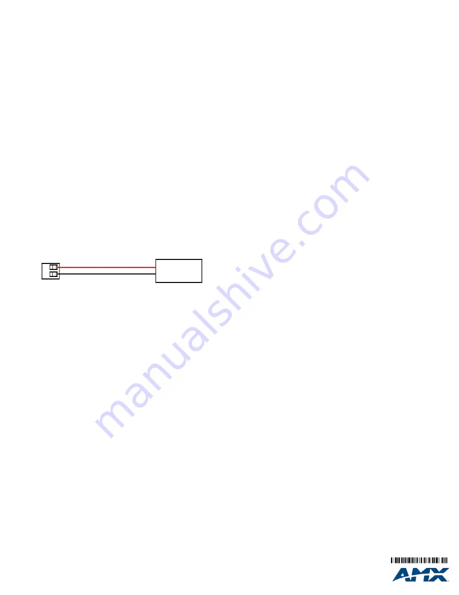
Wiring a power connection
To use the 2-pin 3.5 mm captive wire connector with a 12 VDC-compliant
power supply (PSN4.4 recommended), the incoming PWR and GND wires
from the external source must be connected to their corresponding locations on
the connector (FIG. 3).
1.
Insert the PWR and GND wires on the terminal end of the 2-pin 3.5 mm
captive wire cable.
Match the wiring locations of the +/- on both the
power supply and the terminal connector.
2.
Tighten the clamp to secure the two wires
.
3.
Verify the connection of the 2-pin 3.5 mm captive wire to the external 12
VDC-compliant power supply.
Configuring Communication
Communication between the NXP-PLV panel and the Master is done using
either USB or ETHERNET (DHCP or Static IP). Ethernet communication can
be achieved through a direct connection. For more information on connecting a
NXP-PLV device to your network, refer to the NXP-PLV User Manual, available
at
www.amx.com
.
NOTE:
USB input devices must be plugged into the rear USB connector before
the device is powered up. The device will not detect a USB connection of this
type until after the unit cycles power.
Panel Setup and System Connection
1.
From the
Main
touchscreen page, touch the
Panel Setup
button to open
the
Setup
page.
2.
Press the
Protected Setup
button (located on the lower-left of the panel
page) to open the
Protected Setup
page and display an on-screen key-
pad.
3.
Enter the default password
1988
into the keypad’s password field and
press
Done
when finished.
4.
Press the red
Device Number
field to open the Device Number keypad.
5.
Enter a Device Number for the panel into the Device Number Keypad.
The default is 10001 and the range is from 1 - 32000.
6.
Press
Done
to close the keypad, assign the number, and return to the
Protected Setup
page.
7.
Press the on-screen
Reboot
button to restart the device and incorporate
any changes.
8.
Obtain the System Number and Master IP Address from NetLinx Studio.
This information must be specific for the system used with the configured
NXP-PLV.
9.
Press the
Config
button on the main page to open the
Panel Setup
page.
10. Press the
Protected Setup
button (located on the lower-left of the panel
page) to open the
Protected Setup
page.
11. Press the
System Settings
button (located on the
Protected Setup
page)
to open the
System Settings
page, and begin configuring the communica-
tion settings on the device to match those of the target Master.
NOTE:
The mini-USB connector MUST be plugged into an already active NXP-
PLV before the PC can recognize the connection and assign an appropriate
USB driver. This driver is part of both the NetLinx Studio and TPDesign4
software application installations.
Touchscreen Operation
In addition to the joystick and the side controls, the NXP-PLV has a
touchscreen and six associated Camera Station pushbuttons to control camera
movements and observe the results. Many camera and camera controller
functions, such as presets, may only be accessed through the touchscreen.
For more information on touchscreen features, refer to the NXP-PLV User
Manual, available at
www.amx.com
.
NOTE:
Full touchscreen functionality is only available after download and
installation of the appropriate Cafe Duet module to the master controller. The
module, and the corresponding NetLinx firmware for the NXP-PLV, is available
at
www.amx.com
.
Presets Page
The Presets page is the first screen to appear when the NXP-PLV is first turned
on. The view screen displays a live input feed from a selected camera if the
camera is already connected to the network.
The
Presets
buttons at the top of the screen allow you to choose between one
of one hundred previously saved camera subjects.
The
Camera Stations
external pushbuttons to the left side of the touchscreen
control video feeds from up to six different camera stations: pressing a
particular button switches the device’s influence to that particular station.
Pressing the button for a camera station already selected will change the color
of the accompanying touchscreen tab from green to white, the
Config
button
on the left disappears, and the joystick and side controls are disabled. Click the
button a second time to re-engage the NXP-PLV.
To select a previously saved preset:
1.
From the Presets page, press a button at the top of the screen to move
the camera to that preset position.
2.
To view more presets, press either the left or right arrow to the sides of
the currently displayed presets. For instance, if you are already at default
presets 1 through 10, press the right button to move to presets 11 through
20, and press the left button to view presets 91 through 100.
To save a new preset or to change an existing preset to a new camera position:
1.
Use the joystick to align the camera to the desired position.
2.
Turn the Focus Control knob to focus the image.
3.
Decide upon a Preset number to be saved.
4.
Press and hold the Preset button for 3 seconds. The device will beep
twice when the preset is saved by the device.
5.
Test the new preset by moving the joystick to move the camera and then
pressing the preset button. If the preset was saved, the camera should
move to the selected area.
FIG. 3
NetLinx power connector wiring diagram
PWR +
GND -
To the Touch Panel
Power Supply


