

For full warranty information, refer to the AMX Instruction Manual(s) associated with your Product(s).
1/11
©2011 AMX. All rights reserved. AMX and the AMX logo are registered trademarks of AMX.
AMX reserves the right to alter specifications without notice at any time.
3000 RESEARCH DRIVE, RICHARDSON, TX 75082 • 800.222.0193 • fax 469.624.7153 • technical support 800.932.6993 • www.amx.com
93-2261-09
REV: A
NXD-500IW Setup and System Connection
1.
Carefully remove the panel from the shipping box, peel the protective plastic
cover from the LCD, and apply power to the panel via the PoE Injector.
2.
From below the LCD, press the Front Bezel button for 9 seconds (passing over
the
Setup
page) to access the
Calibration
setup page and follow the on-screen
instructions to return to the main
Setup
page.
3.
Press the on-screen
Protected Setup
button on the
Setup
page.
4.
Enter the panel password into the on-screen keypad (default is
1988)
.
5.
Press the
Device Number
field to open the on-screen Device Number keypad
and enter a value for the panel (
default is 32001
).
6.
Press the
System Connection
button to open the
System Connection
page.
7.
Toggle the
DHCP Static
field to
DHCP
.
8.
Toggle the
Type
field to
Ethernet
.
9.
Toggle the
Mode
field to
URL
.
10.
Enter both the System Number and IP Address of the target Master.
11.
Enter a valid Username and Password if the target Master is secured.
12.
Press the
Back
button and then press the on-screen
Reboot
button to save
any changes and cycle power to the panel.
Installation of the NXD-500IW
For more information on the installation of the NXD-500IW, please refer to the
NXD-
500i Operation/Reference Guide
, available at
www.amx.com
.
The NXD-500IW is contained within a clear outer housing known as the back box
(FIG. 3). This back box is removed when installing the device into a wall or into a
Rough-In Box.
Removing the Bezel
In certain circumstances, the bezel must be removed. Because the device is installed
against a wall, the bezel must be removed carefully to prevent the two top prongs
from being broken. To remove the bezel:
1.
Gently lift up on the bezel from the bottom. Do NOT pull up from the sides or
the top.
2.
Let the bezel fall forward from the top of the device and let it pivot from the bot-
tom.
3.
Remove the bezel from the two bottom prongs.
4.
When reattaching the bezel to the device, make sure to align the Microphone,
Light, and PIR Motion sensor locations on the device to their respective
openings on the bezel assembly.
NOTE:
Do not remove the gasket on the underside of the bezel. If the gasket should
accidentally detach itself, gently reinsert it in the gasket channel running around the
center hole in the bezel. Do NOT stretch the gasket while reinserting it.
Installing the NXD-500IW into a wall
Unlike most AMX touchpanels, the NXD-500IW comes with a clear plastic backbox
(FIG. 7) designed to attach the panel to most standard wall materials. This backbox
has a locking tab on three of the four faces (missing only on the face containing the
space for the connections) to help lock the backbox to the wall. These locking tabs
are only extended AFTER the backbox is inserted into the wall.
WARNING:
When installing the backbox, make sure that the assembly is in the
correct position and in the correct place. Once the locking tabs are extended and
locked into place, removing the backbox may be difficult without having access to the
back of the wall or causing damage to the wall.
Note:
In order to guarantee a stable installation of the NXD-500IW, the thickness of
the wall material must be a minimum of .50 inches (1.27cm) and a maximum of .875
inches (2.22cm).
WARNING:
The maximum recommended torque to screw in the locking tabs on the
plastic back box is 5 IN-LB [56 N-CM]. Applying excessive torque while tightening the
tab screws, such as with powered screwdrivers, can strip out the locking tabs or
damage the plastic back box.
1.
Prepare the area by removing any screws or nails from the drywall before
beginning the cutout process.
2.
Cut out the surface for the back box. Refer to the dimensions in the
NXCD-500i
Operation/Reference Guide
, available from
www.amx.com
, for more
information.
CAUTION:
Making sure that the actual cutout opening be slightly smaller than the
provided dimensions is highly recommended. This action provides the installer with a
margin for error if the opening needs to be expanded. Too little wall material removed
is always better than too much.
3.
Remove the bezel from the NXD-500IW.
4.
Gently unscrew the two screws attaching the NXD-500IW to its back box.
These are at the bottom of the device, underneath the touch screen. Carefully
remove the NXD-500IW from the back box.
NOTE:
While the screws are loosened, you can adjust the LCD to ensure that it is
parallel to the sides of the backbox, if necessary. While adjusting the LCD is
possible, it is not required in most cases.
5.
Thread the incoming Ethernet and mini-USB wiring (if mini-USB access is
desired) from their terminal locations through the surface opening.
Leave
enough slack in the wiring to accommodate any re-positioning of the panel.
6.
Push the back box into the wall opening. Insure that the locking tabs lie flush
against the back box.
7.
Extend the locking tabs on the sides of the back box by tightening the screws
inside the box until snug. Not all of the tabs must be extended to lock the back
box in place, but extending a minimum of the top and bottom tabs is highly
recommended. Apply enough pressure to the screw head to keep the box flush
with the wall: this ensures that the locking tabs will tighten up against the inside
of the wall.
The back box is clear to allow visual confirmation that the tabs have been
extended and are gripping the wall, as well as in assisting with removal if
necessary
8.
Insert both connectors into their corresponding locations along the left side of
the NXD-500IW touch panel.
9.
Test the incoming wiring by attaching the panel connections to their terminal
locations and applying power via the PoE Injector. Verify that the panel is
receiving power and functioning properly to prevent repetition of the
installation.
NOTE:
Do not disconnect the connectors from the touch panel. The unit must be
installed with the attached connectors before being inserted into the drywall.
10.
Insert the NXD-500IW back into the back box.
11.
The microphone cable is taped to the back box. Connect the microphone cable
to its connector, making sure that the cable does not interfere with
reattachment of the bezel.
12.
Carefully replace the two Plastite screws holding the device to the back box.
13.
Place the bezel/Trim Ring assembly back onto the device. Make sure to align
the Microphone, Light, and PIR Motion sensor locations to their respective
openings on the bezel.
14.
Reconnect the terminal Ethernet and USB to their respective locations on
either the Ethernet port or NetLinx Master.
Installing the NXD-500IW into a Flat Surface using #4 screws
Three #4 mounting screws (not included) are secured through circular holes located
at the left and right sides of the NXD-500IW. The most important thing to remember
when mounting the NXD-500IW is that the outer frame (Mounting Tabs) must be
installed flush against the mounting surface.
•
Refer to SP-2261-02 for detailed installation dimensions.
•
Cutting out the surface slightly smaller than what is outlined in the installation
drawings in order to make any necessary cutout adjustments, is highly
recommended.
1.
Prepare the area by removing any screws or nails from the surface before
beginning the cutout process.
2.
Cut out the surface for the NXD-500IW.
3.
Remove the bezel from the NXD-500IW.
4.
Gently unscrew the lower right-hand screw attaching the NXD-500IW to its
back box. These are at the bottom of the device, underneath the touch screen.
Gently remove the NXD-500IW from the back box.
5.
Thread the incoming Ethernet and USB wiring from their terminal sources
through the surface opening. Leave enough slack in the wiring to
accommodate any re-positioning of the panel.
6.
Connect the Ethernet and USB connectors to their corresponding locations
along the left side of the un-powered NXD-500IW touch panel. The USB
connectors can be from either a USB extension cable or a wireless USB RF
transmitter.
NOTE:
Do not disconnect the connectors from the touch panel. The unit must be
installed with the necessary connectors before being inserted into the solid surface.
7.
Carefully slide the main unit into the cutout until the Mounting Tabs of the
NXD-500i lie flush against the wall.
8.
Insert and secure three #4 Mounting Screws (not included) into the
corresponding holes located along the sides of the NXD-500IW, using a
grounded Phillips-head screwdriver, until the unit is secure and flush against
the wall.
9.
The microphone cable is taped to the back box. Connect the microphone cable
to its connector, making sure that the cable does not interfere with
reattachment of the bezel.
10.
Carefully replace the two Plastite screws holding the device to the back box.
11.
Place the bezel back onto the device.
Make sure to align the Microphone,
Light, and PIR Motion sensor locations to their respective openings on the
bezel.
12.
Reconnect the terminal Ethernet and USB to their respective locations on
either the Ethernet port or NetLinx Master.
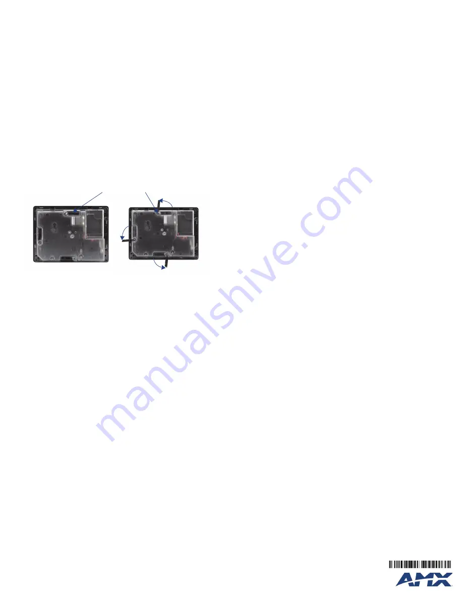
FIG. 3
NXD-500IW backbox with closed and open locking tabs
Locking tabs - Closed
Locking tabs - Open
Locking tab screws


