

Installation Guide
NXA-BEZP-435
Portrait Bezel Kit
For more detailed installation, configuration, programming, file transfer, and
operating instructions for the NXD-435, refer to the
NXD-435 Operation
Reference Manual
, available online at
www.amx.com
.
Overview
The NXA-BEZP-435xx is a kit solution that allows the NXD-435 touch panel to be
installed in portrait mode, where the vertical dimension of the touch screen is larger
than the horizontal, instead of its traditional landscape mode. The NXA-BEZP-435 is
available in black (NXA-BEZP-435-BL,
FG2262-12
) or white (NXA-BEZP-435-WH,
FG2261-13
).
Note:
Use of the NXD-435 in portrait mode requires the latest versions of the
TPDesign4 application and of the AMX NXD-435 landscape mode firmware, version
XX.XX.XX or higher. Both are available for download from
www.amx.com
.
Specifications
Panel Connectors and Wiring
FIG. 2 shows the connectors located on the NXD-435 Modero panel. The mini-USB
port is used for programming the touch panel.
For more information on connection and use of the Panel Connectors, as well as
information on programming, please refer to the
NXD-435 User Manual
, available at
www.amx.com
.
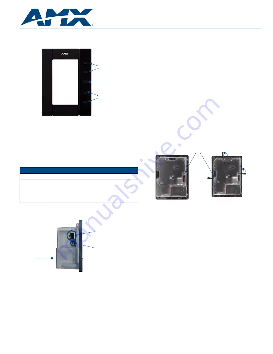
Capacitive Touch Buttons
The NXD-435 has one main button on the front of the device, in the center of the
bezel. This button has several uses:
•
Press the button once to start a previously programmed function, or to turn off
the display if not previously programmed.
•
Press and hold the button for 6 seconds to put the device into
Setup Mode
.
•
Press and hold the button for 9 seconds to enter
Calibration Mode
.
•
Press and hold the button for 20 seconds to reboot the panel.
The NXD-435 also has four smaller buttons, two above and two below the front
button, that may be programmed for individual functions.
NXD-435 Setup and System Connection
1.
Carefully remove the panel from the shipping box, peel the protective plastic
cover from the LCD, and apply power to the panel via the PoE Injector.
2.
From below the LCD, press the front button for 9 seconds (passing over the
Setup
page) to access the
Calibration
setup page and follow the on-screen
instructions to return to the main
Setup
page.
3.
Press the on-screen
Protected Setup
button on the
Setup
page.
4.
Enter the panel password into the on-screen keypad (default is
1988)
.
5.
Press the
Device Number
field to open the on-screen Device Number keypad
and enter a value for the panel (
default is 32001
).
6.
Press the
System Settings
button to open the
System Settings
page.
7.
From the
IP
tab, toggle the
DHCP Static
field to
DHCP
if it is not already set to
DHCP.
8.
From the
Master
tab, toggle the
Type
field to
Ethernet
.
•
Toggle the
Mode
field to
URL
.
•
Enter both the System Number and IP Address of the target Master.
9.
Enter a valid Username and Password if the target Master is secured.
10.
Press the
Back
button and then press the on-screen
Reboot
button to save any
changes and cycle power to the panel.
Installation of the NXA-BEZP-435
The NXD-435 can be installed either directly into the (optional) CB-TP5I Rough-In Box
or another solid surface environment, using either solid surface screws or the included
locking tabs for different mounting options. For more information, please refer to the
NXD-435 User Manual, available at
www.amx.com
.
The NXD-435 is contained within a clear outer housing known as the back box
(FIG. 3). This back box is not removed when installing the device into a wall or into a
Rough-In Box.
Removing the Bezel
In order for the NXD-435 to be used in portrait mode, the existing bezel must be
removed and replaced with the bezel from the Portrait Bezel Kit. Because the device is
installed against a wall, the bezel must be removed carefully to prevent the two prongs
at the top of the device from being broken. To remove the bezel:
1.
Hold the NXD-435 with the AMX logo on the bezel at the top. Gently lift up on the
installed bezel from the bottom. Do NOT pull up from the sides or the top.
2.
Let the bezel fall forward from the top of the device and let it pivot from the
bottom of the device.
3.
Remove the bezel from the two bottom prongs.
4.
Carefully disconnect the capacitive touch connector to the 10-pin plug on the
bezel.
5.
Install the NXD-435 into its intended location (refer to the installation instructions
below for more information).
6.
Carefully connect the capacitive touch connector to the 10-pin plug on the bezel.
7.
With the NXD-435 in its intended portrait position, place the NXA-BEZP-435
bezel on the device, gently hooking the prongs on the bezel on both the left and
right sides. Gently push the bezel to the right to lock it into place.
Installing the NXD-435 into a wall in Portrait Mode
Unlike most AMX touchpanels, the NXD-435 comes with a clear plastic backbox
(FIG. 3) designed to attach the panel to most standard wall materials. This backbox
has a locking tab on three of the four faces (missing only on the face containing the
space for the connections) to help lock the backbox to the wall. These locking tabs are
only extended AFTER the backbox is inserted into the wall.
WARNING:
When installing the backbox, make sure that the assembly is in the correct
position and in the correct place. Once the locking tabs are extended and locked into
place, removing the backbox may be difficult without having access to the back of the
wall or causing damage to the wall.
Note:
In order to guarantee a stable installation of the NXD-435, the thickness of the
wall material must be a minimum of .50 inches (1.27cm) and a maximum of .875
inches (2.22cm).
FIG. 1
NXA-435-BL 4.3"
Portrait Bezel for the NXD-435 Touch Panel
NXA-BEZP-435xx (FG2262-12/13) Specifications
Dimensions (HWD):
• NXD-435: 4.13" x 5.5” x 0.50" (10.48 cm x 13.97 cm x 1.27 cm)
Weight:
• 0.10 lbs (45.36 kg)
Included
Accessories:
• NXD-435 Installation Guide (
93-2262-01
)
Other AMX
Equipment:
• NXD-435 (
FG2262-03/04
)
FIG. 2
Connector layout on the NXD-435 Modero Wall/Flush Touch Panel
Center Button
Capacitive Touch Buttons
Capacitive Touch Buttons
Ethernet 10/100 port
Mini-USB port
Back box
FIG. 3
NXD-435 backbox with closed and open locking tabs
Locking tabs - Closed
Locking tabs - Open
Locking tab screws


