background image

Encoder Configuration Options

40

 N2151/N2251 User Manual
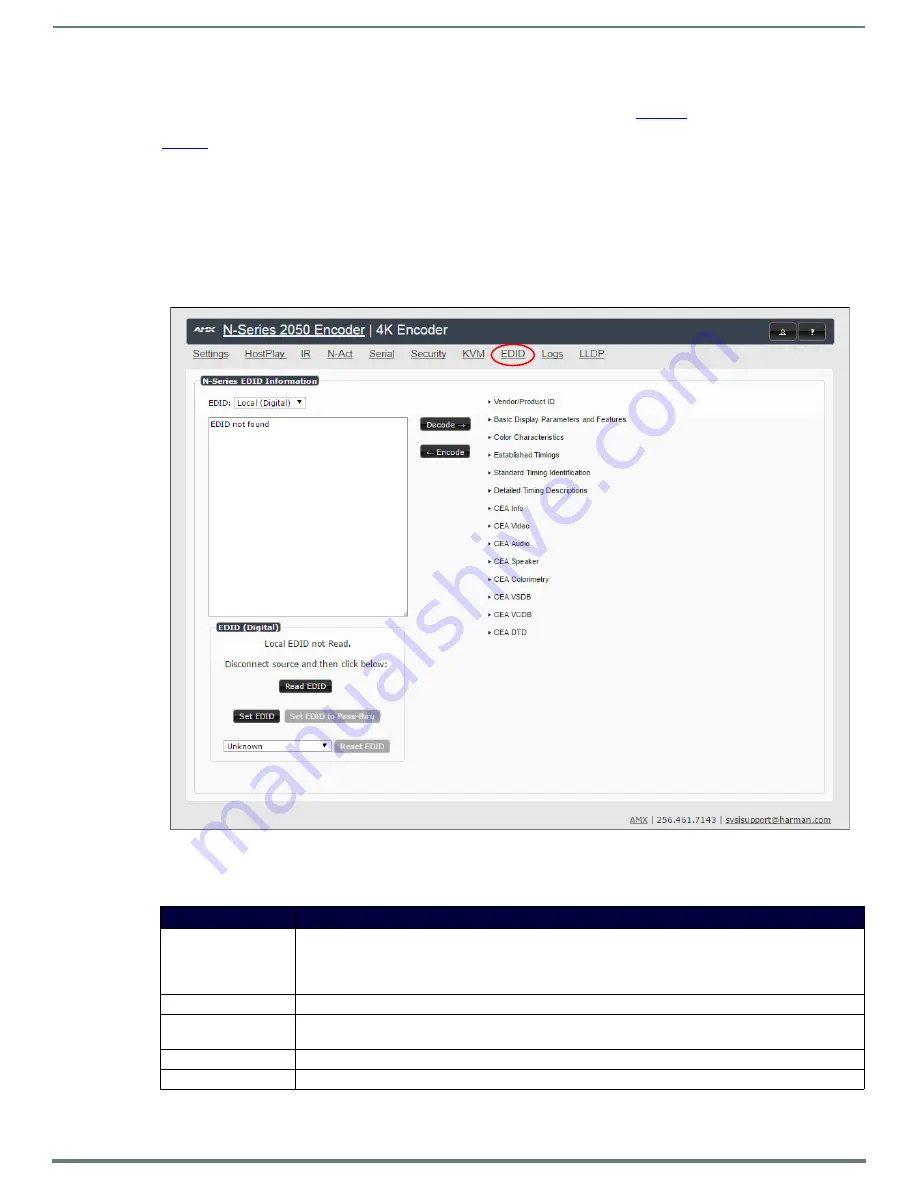
EDID Page

Click the 

EDID

 link at the top of any of the main web pages to access the page shown in 

Figure 35

. Every display has stored 

information that it communicates to the output device. This page allows you to view that information.Options are described in 

Table 14

Edit the Encoder’s EDID if you need to change the display options available to the source. There are four different ways to 

control the EDID of the Encoders. 

Option 1: 

Use the default settings drop-down menu and select from the options available. Then click 

Set EDID

. This will work for 

most sources and is most often set to 

Stereo (2 channel)

Option 2: 

When using an EDID captured from a display connected to a Decoder, paste the data in to the white EDID block, 

overwriting existing EDID. Then click 

Set EDID

Option 3:

 Make changes to the operating parameters displayed on the right side of the screen. Use the 

Encode

 button to translate 

the changes into a new EDID and click 

Set EDID

.

Option 4: 

Connect a compatible display to the Encoder's 

HDMI Out

 port and click 

Set EDID to Pass-thru

.

NOTE: 

The source will need to be disconnected while modifying EDID settings.

FIG. 35  

EDID Page

TABLE 14  

EDID Page Options 

Option

Description

EDID drop-down box

Select what EDID information to display. 

Pass-thru:

 Displays EDID information for the display connected to the Encoder’s pass thru port.

Local (Digital/Analog)

: Displays EDID information for the Encoder. This information is being provided to the 

source connected to the Encoder.

Decode button

Click to translate the EDID currently displayed on the left to the operating parameters list on the right.

Encode button

After making any changes to the operating parameters list on the right, click this button to update the EDID 

information on the left. To store the new settings, click 

Set EDID

.

Read EDID

Click to initially show the EDID or if the source EDID has changed (refreshes the EDID table).

Set EDID

If creating a custom EDID, click to apply the changes.

Summary of Contents for NMX-DEC-N2251

Page 1: ...INSTRUCTION MANUAL N2151 N2251 ENCODERS DECODERS 4K DIGITAL MEDIA DISTRIBUTION SWITCHING SOLUTION NMX ENC N2151 NMX DEC N2251 ...

Page 2: ... outlet 10 PROTECT the power cord from being walked on or pinched particularly at plugs convenience receptacles and the point where they exit from the apparatus 11 ONLY USE attachments accessories specified by the manufacturer 12 UNPLUG this apparatus during lightning storms or when unused for long periods of time 13 REFER all servicing to qualified service personnel Servicing is required when the...

Page 3: ...etween the equipment and receiver Connect the equipment into an outlet on a circuit different from that to which the receiver is connected Consult the dealer or an experienced radio TV technician for help Approved under the verification provision of FCC Part 15 as a Class A Digital Device Caution Changes or modifications not expressly approved by the manufacturer could void the user s authority to...

Page 4: ...ually using the Settings page 18 Option 2 Assigning IP Addresses to Multiple Units using CSV files 18 Switching and Scaling Options 20 Seamless Switching 20 Control Options 21 Primary Control Options 21 N Command Controllers 21 Third Party Controllers 21 N Act On Board Built In Control 21 N Touch IP Wall Controller 21 KVM Configuration 22 Basic Setup 22 Video USB Switching Options 22 Advanced KVM ...

Page 5: ...p Section 44 Advanced Settings 46 RS232 Settings 48 Network Setup Section 48 Status Section 49 Change Password Section 50 Software Section 50 Audio Downmixer Settings 51 LocalPlay Page 53 IR Page 54 N Act Page 55 Serial Page 56 Security Page 57 KVM Page 58 EDID Page 59 Logs Page 60 LLDP Page 60 Troubleshooting 61 Series Default Local Host Play Troubleshooting Screens 62 Appendix A Minimum Network ...

Page 6: ...ude classrooms conference rooms performing arts centers and sports bars Features include Output Scaling Video scaling at the output Decoder allows seamless switching from any source at any resolution to any display or projector while preserving video fidelity Infrared IR Infrared emitter connection allows control of low cost IR only display devices Onboard Control All N Series Encoders and Decoder...

Page 7: ... hold for 30 seconds to initiate a factory restore POWER LED On solid green when operating power is supplied via local power supply This activity is also shown by the PWR LED on the rear panel STATUS LED On flashing green when there is software activity This activity is also shown by the STAT LED on the rear panel Rear Panel 12V 2A 12 Volt DC power input PWR LED Same as POWER LED described above H...

Page 8: ...ser selectable balanced unbalanced dedicated audio input for Encoders and output for Decoders HDMI IN HDMI video input Encoders HDMI OUT HDMI video output Decoders Pass thru HDMI video Encoders VGA IN DB 15 analog input Allows for the use of analog video sources Applies to Encoders only Front and Rear Panel Descriptions Cont ...

Page 9: ...port using a video cable with a VGA connector or component adapter For local viewing of pass thru video connect a digital display to the Encoder s HDMI OUT port using a video cable with an HDMI connector or adapter N2251 Decoders For video decoding connect a digital display to the Decoder s HDMI OUT port using a video cable with an HDMI connector or adapter Audio N2151 Encoders For audio encoding ...

Page 10: ...for more information on these connections FIG 5 Installing Mounting Wings Rack Mounting N2X51 Series Stand Alone Units The N Series 1RU Rack Shelf part number NMX ACC N9102 accommodates up to two stand alone N Series Encoders or Decoders side by side any combination of product series FIG 6 Rack Mounting Stand Alone Units N2X51 Series Cards The N Series Card Cage part number NMX ACC N9206 accommoda...

Page 11: ...ts 5 Repeat these steps until all cards are properly installed See Figure 8 FIG 8 Fully Populated Card Cage 6 For proper airflow cover any unused card slots with faceplate blanks Blanks are sold separately part number N9210 7 Make sure the Card Cage s power cord is plugged in for proper cooling The POWER LED on the front of the cage should always be on CAUTION Keep the Card Cage s power cord plugg...

Page 12: ...200x800 have been constructed on a house network using N Series equipment Alternatively many customers choose to deploy on physically separate networks in order to use low cost network appliances but keep video traffic separate from data and voice 3 N Able software has been loaded on the computer you are using to configure the equipment From your host computer download N Able our free setup utilit...

Page 13: ...ent 13 N2151 N2251 User Manual 3 Double click the wired interface to your AV network and then click the Properties button 4 Scroll down in the list to the Internet Protocol Version 4 TCP IPv4 option Highlight it and click the Properties button ...

Page 14: ...ever some display devices e g many monitors do not support embedded audio When using such a display use the AUDIO port for separate transmission of sound and turn HDMI Audio off on the Settings page to avoid video display issues Power is supplied via an external power supply Refer to the following steps and Figure 9 for guidance 1 Using a Cat 5e or higher cable connect your N2251 Decoder s P0 port...

Page 15: ...k plug connector labeled 12V 2A 3 In N Able select the Unit Management tab and click the Auto Discover button if the table has not already populated itself with the installed units See Figure 10 FIG 10 Unit Management Page 4 Find your Encoder in the list N2X51 units are displayed on the following tabs Unit Management tab N2X51 units have N Series 4K Encoder Decoder listed in their Type fields Vide...

Page 16: ...modified under N Able Settings 6 The Settings page is displayed see Figure 13 7 Change the Stream setting We recommend setting Stream to a number between 2 and 254 it is required that the number be less than 32 512 Use the P0 and P1 check boxes to designate which port to send the stream over NOTE Uncompressed streams 880 4250 Mbps are only supported on the P1 port Compressed streams 200 600 Mbps a...

Page 17: ...irst connected to the network an IP address is assigned automatically based on the network DHCP server If no DHCP server is found the unit will use Auto IP mode with an IP address pre configured to 169 254 xxx xxx with a subnet mask of 255 255 0 0 How IP Address Changes Affect Unit Control As discussed previously N Able control is dependent upon the host computer being in the same IP address range...

Page 18: ...ppropriate devices Reboot the devices to activate the new settings This procedure can be used to configure multiple networked AV devices at the same time It can also provide valuable diagnostics by allowing you to see the last known device configuration as well as scan the network for new devices regardless of IP configuration To configure units using a CSV file follow these steps 1 Make sure that...

Page 19: ...Installing and Configuring Your AV Equipment 19 N2151 N2251 User Manual FIG 15 Encoder Connection to Source N2151 Encoder Switch Network HDMI Cable Cat 5 Cable ...

Page 20: ...are not available when input is 3840x2160 50 3840x2160 59 97 3840x2160 60 4096x2160 50 4096x2160 59 97 or 4096x2160 60 Seamless Switching The N2X51 Series supports seamless switching capability if the scalers in the Decoders are all set to the same resolution and refresh rate If the scalers are off all of the sources must have the same resolution and refresh rate To get streams onto a Decoder use ...

Page 21: ...s hot swappable drives and redundant power supplies Graphical presentation of video network connections Full configuration control assign fixed IP addresses for each N Series component adjust variable bit rate for each video stream etc Additional software bundles free with N Command allow you to easily create attractive touch panels for N Series and third party equipment control as well as build s...

Page 22: ...cting video Independent Video Switching To switch video streams without affecting USB control first select N Able Settings from N Able s main menu When the N Able Settings dialog box is displayed disable the USB follows Video switching for KVM units Now you can use the Video Matrix to switch video streams only Advanced KVM Setup With Added Security Features You can configure devices for more advan...

Page 23: ...n also be managed in the unit s GUI by clicking KVM from the main menu as shown in Figure 18 It is important to note that many of these options only appear on the KVM page when USB is enabled as well as KVM Advanced Settings See KVM Page on page 58 for more details FIG 18 Selecting the KVM Page ...

Page 24: ...in the GUI you can access all other main pages by clicking the links in the top navigation bar Figure 19 shows the navigation bar and provides hot links to the sections of this chapter which describe each main page FIG 19 Section Links N Act Page on page 36 Security Page on page 38 KVM Page on page 39 EDID Page on page 40 Logs Page on page 41 LLDP Page on page 41 Settings Page on page 25 HostPlay ...

Page 25: ...ons and also has links to other dialog boxes for additional configuration options Refer to the following sections for detailed descriptions Encoder Setup Section on page 26 Advanced Settings on page 28 RS232 Settings on page 30 Network Setup Section on page 30 Status Section on page 31 Change Password Section on page 32 Software Section on page 32 HDMI Pass Thru Settings Section on page 33 FIG 20 ...

Page 26: ...lly Avoid using special characters TX Enable Enable to generate and transmit multicast streams Compressed Stream View edit the current transmit compressed stream number Enable the port you wish to transmit the stream on P0 or P1 To better understand this setting think of Encoders more like a channel on a cable box rather than a traditional AV Matrix Each Encoder must have a unique stream number ju...

Page 27: ... unplugged it will automatically fall back to analog audio if there is an analog source plugged in Color Space Correction Set the color space settings for the Encoder YcbCr RGB to be disabled enabled or selected automatically based on the source If you see a pink green washed out screen across the entire image this can be changed by modifying color space settings Most sources function with Auto se...

Page 28: ...making changes or a user from manually making changes Input Level Gain Left Right Select a PRE ENCODE cut in the audio signal This can help prevent distortion of the audio when the source is providing audio that is too loud clipping Setting does not affect digital audio Audio Gain Slide right to provide a POST ENCODE boost in the audio signal to both left and right channels This can help compensat...

Page 29: ...cs Determine how often in seconds the unit transmits discovery packets TTL Select the Time To Live TTL for the transmit audio and video streams Limits the lifespan of data on the transmit audio and video streams to improve performance DSCP Select the Differentiated Services Code Point DSCP for the transmit audio and video streams Serial Master Enable Enable this device to be the master to the desi...

Page 30: ...69 254 1 1 will be automatically assigned to the N2151 Encoder by the control software When set to DHCP an IP Address in the range of the DHCP server on the network will be automatically assigned to the N2151 Encoder When set to STATIC an IP address Netmask and Gateway address must be manually entered DHCP is the default setting However using DHCP beyond initial setup is generally not recommended ...

Page 31: ...updated compressed bandwidth Output bandwidth shown even if transmit is disabled Port 50001 Source IP Shows the IP address of the currently connected device or displays Disconnected if no connection exists Port 50001 can only accept a single external connection at a time If a device is currently showing the port occupied by a control system or other device then other connections will be rejected H...

Page 32: ... in Figure 27 Options are described in Table 6 FIG 27 Software Section TABLE 6 Settings Page Software Section Option Description Serial Displays the serial number of the N2151 Encoder MAC Address Displays the MAC address of the network interface of the N2151 Encoder Firmware Version Displays the date code for the currently running version of the N2151 Encoder internal firmware Web Version Displays...

Page 33: ...he HDMI connection Selecting Auto bases audio output on the settings of the connected source device YCbCr 4 2 2 Output For color conversion Can force to RGB output based on connected device s reported settings Default and preferred setting is Off Simplified HDMI Detect When enabled detects HDMI solely based on the hot plug detection Enable to help prevent displays monitors from going to sleep Inve...

Page 34: ...ears in the list a transition time can be set for each image Save This List Click to save the current configuration Name Enter a name for the playlist Output Mode Select the HostPlay output resolution The playlists that were uploaded in that resolution are then displayed for your selection Audio Choose an audio file to play while the HostPlay image is on the screen Image list Allows you to customi...

Page 35: ...Commands can be saved for future use and executed later The IR Code menu lists all saved IR commands See Table 9 for option descriptions FIG 30 IR Page TABLE 9 IR Page Options Option Description IR Code Create select IR codes Different vendors have different IR Pronto codes and can usually be found through a web search Copy paste new IR commands directly into the input space Save Save the current ...

Page 36: ...be performed when the Encoder powers on Visit our website for more details on Application Programming Interface API commands Video Cable Connected Event Create delete test events to be performed when the Encoder is connected to a video source The Trigger Delay field specifies how long the device has to be connected for the command to be executed Video Cable Disconnected Event Create delete test ev...

Page 37: ...e sending commands from the Serial page will always return a No Data message and fail to send the commands FIG 32 Serial Page TABLE 11 Serial Page Options Option Description Serial Code Create select serial commands Different vendors have different codes that can usually be found through a web search Copy paste new commands in either ASCII or HEX directly into the appropriate input space Save Save...

Page 38: ...33 Security Page TABLE 12 Security Page Options Option Description General Security This section allows you to force HTTPS connections and set up a default password for stream encryption To successfully communicate the Decoder must know and match the Encoder password Command Port Security This section allows you to secure the port connections for TCP port addresses 50101 50102 and 50104 These port...

Page 39: ...he same time maximum is 100 connections See the section Advanced KVM Setup With Added Security Features on page 22 for more information Permission Level Set the permission level for the Encoder Decoders can only establish USB connection to Encoders with the same or higher permission level See the section Advanced KVM Setup With Added Security Features on page 22 for more information Import KVM CSV...

Page 40: ...ide of the screen Use the Encode button to translate the changes into a new EDID and click Set EDID Option 4 Connect a compatible display to the Encoder s HDMI Out port and click Set EDID to Pass thru NOTE The source will need to be disconnected while modifying EDID settings FIG 35 EDID Page TABLE 14 EDID Page Options Option Description EDID drop down box Select what EDID information to display Pa...

Page 41: ...create the file You can then download and send it to AMX support FIG 36 Logs Page NOTE For security reasons only use the Enable Maintenance Mode if instructed to by SVSI AMX Technical Support LLDP Page Click the LLDP link at the top of any of the main web pages to access the page shown in Figure 37 The LLDP page displays information from the Link Layer Discover Protocol LLDP packet which identifie...

Page 42: ...section on page 24 you can access the GUI main pages by clicking the links in the top navigation bar Figure 38 shows the navigation bar and provides hot links to the sections of this chapter which describe each main page FIG 38 Section Links Settings Page on page 43 Audio Downmixer Settings on page 51 LocalPlay Page on page 53 IR Page on page 54 Security Page on page 57 KVM Page on page 58 EDID Pa...

Page 43: ...ections and also has links to other dialog boxes for additional configuration options Refer to the following sections for detailed descriptions Decoder Setup Section on page 44 Advanced Settings on page 46 RS232 Settings on page 48 Network Setup Section on page 48 Status Section on page 49 Change Password Section on page 50 Software Section on page 50 Audio Downmixer Settings on page 51 FIG 39 Set...

Page 44: ...d this setting think of Decoders dialing up channels on a cable box rather than a traditional AV matrix Each Decoder can dial in a different active channel Audio Stream View edit the current audio receive stream number Audio Follows Video Enable to force the Audio Stream to the same as the video stream Scaler Enable to scale outgoing content to a fixed resolution or to use the Crop Pan Zoom functi...

Page 45: ...io Advanced Settings Refer to Advanced Settings on page 46 for details on the options available from this link RS232 Settings Refer to RS232 Settings on page 48 for details on the options available from this link Allow SVSI Multicast Disable this option to prevent the port from outputting multicast video traffic Particularly useful if you are connecting a non SVSI device to a port for network base...

Page 46: ... from manually making changes Input audio for LocalPlay Select to enable the input audio when the Live Local menu is set to one of the local images YCbCr 4 2 2 Output Set YCbCr output to be disabled enabled or selected automatically based on the connected display Simplified HDMI Detect Select to enable the detection of a display device using a simple line level check Last Frame Hold Select to caus...

Page 47: ...ode Can be disabled to start responding again Serial Slave Address Enter the IP address of the serial slave device IR Command Holdoff Set the delay between IR command portions The default setting is 25 ms IR commands are sent in two parts This setting is the time in milliseconds between transmission of part one and part two The second part of the command is inverted for confirmation purposes IR Re...

Page 48: ... 169 254 1 1 will be automatically assigned to the N2251 Decoder by the control software When set to DHCP an IP Address in the range of the DHCP server on the network will be automatically assigned to the N2251 Decoder When set to STATIC an IP address Netmask and Gateway address must be manually entered DHCP is the default setting However using DHCP beyond initial setup is generally not recommende...

Page 49: ...ime If a device is currently showing the port occupied by a control system or other device then other connections will be rejected However connection attempts from the same IP will override the current connection Port 50002 Source IP Shows the IP address of the currently connected device or displays Disconnected if no connection exists Port 50002 can only accept a single external connection at a t...

Page 50: ...in Figure 46 Options are described in Table 20 FIG 46 Software Section TABLE 20 Settings Page Software Section Option Description Serial Displays the serial number of the N2251 Decoder MAC Address Displays the MAC address of the network interface of the N2251 Decoder Firmware Version Displays the date code for the currently running version of the N2251 Decoder internal firmware Web Version Display...

Page 51: ...o source Center Gain slider Set percentage of audio on center channel mixed into left and right output when downmixing Front Gain slider Set percentage of audio on front left and right channels mixed into left and right output respectively Surround Gain slider Set percentage of audio on surround when downmixing left and right channels mixed into left and right output respectively Line out source S...

Page 52: ...ling features are not available when input is 3840x2160 59 97 3840x2160 60 4096x2160 59 97 or 4096x2160 60 TABLE 23 Crop Pan Zoom Page Options Option Description X1 Y1 Set pixel coordinates of viewing area top left X2 Y2 Set pixel coordinates of viewing area bottom right 16 9 Aspect Ratio Enable to force to a 16 9 ratio No Crop Click to disable existing crop settings and return unit to default out...

Page 53: ...e drop down menu to view edit the images currently used in the chosen image playlists If more than one image appears in the list a transition time can be set for each image Save This List Click to save the current configuration Name View edit playlist names Output Mode Select the resolution you want the image s to play in Audio Select an audio file to play while the LocalPlay image is on the scree...

Page 54: ...commands See Table 25 for option descriptions FIG 50 IR Page Delete Image s Delete the selected image file from the playlist Delete Audio Delete the selected audio file from the playlist TABLE 24 LocalPlay Page Options Cont Option Description TABLE 25 IR Page Options Option Description IR Code Create select IR codes Different vendors have different IR Pronto codes and can usually be found through ...

Page 55: ...elete test events to be performed when the Decoder powers on Visit our website for more details on Application Programming Interface API commands Video Cable Connected Event Create delete test events to be performed when the Decoder is connected to an output display The Trigger Delay field specifies how long the device has to be connected for the command to be executed Video Cable Disconnected Eve...

Page 56: ...e sending commands from the Serial page will always return a No Data message and fail to send the commands FIG 52 Serial Page TABLE 27 Serial Page Options Option Description Serial Code Create select serial commands Different vendors have different codes that can usually be found through a web search Copy paste new commands in either ASCII or HEX directly into the appropriate input space Save Save...

Page 57: ...53 Security Page TABLE 28 Security Page Options Option Description General Security This section allows you to force HTTPS connections and set up a default password for stream encryption To successfully communicate the Decoder must know and match the Encoder password Command Port Security This section allows you to secure the port connections for TCP port addresses 50101 50102 and 50104 These port...

Page 58: ... See the section Advanced KVM Setup With Added Security Features on page 22 for more information Connect to Encoder IP Address Enter the IP Address of an active Encoder Use the Switch and Disconnect buttons to control the connection KVM Advanced Settings Enable to access the KVM Encoders list KVM Encoders View edit the list of Encoders associated with this Decoder Here you can Add new overwrite En...

Page 59: ...nload KVM CSV Export link to retrieve the current KVM CSV configuration file Reset USB and KVM Settings Resets all USB and KVM settings TABLE 29 KVM Page Options Cont Option Description TABLE 30 EDID Page Options Option Description EDID Display Shows the EDID of the display that is connected to the Decoder Decode button Click to translate the EDID currently displayed on the left to the operating p...

Page 60: ...g section to capture information useful for troubleshooting Simply click Start Debug Log wait at least one minute and click End Debug Log to create the file You can then download and send it to AMX support FIG 56 Logs Page NOTE For security reasons only use the Enable Maintenance Mode if instructed to by SVSI AMX Technical Support LLDP Page Click the LLDP link at the top of any of the main web pag...

Page 61: ... mentioned previously in this table you can change to the Local mode on the Decoder s Settings page If LocalPlay appears set Decoder to Live play mode and verify network is configured properly No audio is detected If there is no audio on all Decoders verify audio settings are correct on Encoder If there is no audio on a single Decoder verify audio settings are correct on Decoder Device has been di...

Page 62: ...coder stream on the network is set to HostPlay or does NOT have a valid input video signal Seeing this screen means that the Decoder CAN communicate with the Encoder across the network It is a good way to troubleshoot network communication between segments using only Encoders and Decoders without the need for source video into an Encoder Displayed when Decoder Notes is set to LocalPlay mode If the...

Page 63: ...iving the stream from the intended Encoder However the video signal being sent to the Encoder is not supported Please visit amx com and refer to the product pages for the supported resolutions lists Displayed when Decoder and Encoder Notes is receiving a stream from an Encoder is connected to a monitor that does NOT support Restricted Content i e the monitor is NOT HDCP compliant is transmitting H...

Page 64: ...e video source but is not set up to pass it Please call Technical Support to enable this feature Displayed when Decoder Notes is receiving a stream from an Encoder it can not decrypt Make sure the Decoder has the correct password for decrypting the stream To reset the password go to the Security page on both the Encoder and Decoder and click the Reset button Refer to the Security Page section on p...

Page 65: ...wait for a response to a group specific or group and source specific query message Immediate Leave also know as Fast Leave etc depending on switch manufacturer NOTE If Immediate Leave is disabled set IGMP Robustness to Default 2 Robustness can be adjusted generally from 2 10 The higher the value the more leave latency is added Warnings Notices There is a known behavior within IGMP that Encoder str...

Page 66: ...responsibility for errors or omissions AMX also reserves the right to alter specifications without prior notice at any time The AMX Warranty and Return Policy and related documents can be viewed downloaded at www amx com 3000 RESEARCH DRIVE RICHARDSON TX 75082 AMX com 800 222 0193 469 624 8000 1 469 624 7400 fax 469 624 7153 AMX UK LTD AMX by HARMAN Unit C Auster Road Clifton Moor York YO30 4GD Un...

Reviews: