

For full warranty information, refer to the AMX Instruction Manual(s) associated with your Product(s).
8/14
©2014 AMX. All rights reserved. AMX and the AMX logo are registered trademarks of AMX.
AMX reserves the right to alter specifications without notice at any time.
3000 RESEARCH DRIVE, RICHARDSON, TX 75082 • 800.222.0193 • fax 469.624.7153 • technical support 800.932.6993 • www.amx.com
93-5968-08
REV: K
6. Push the Backbox into the mounting surface. Insure that the locking tabs lie flush against
the Backbox and that the Backbox goes freely into the opening.
7. Extend the locking tabs on the sides of the Backbox by tightening the screws inside the
box until snug.
Apply enough pressure to the screw head to keep the box flush with the wall: this
ensures that the locking tabs will tighten up against the inside of the wall.
The Backbox is clear to allow visual confirmation that the tabs have been extended and
are gripping the wall, as well as in assisting with removal if necessary.
Note
: The maximum recommended torque to screw in the locking tabs on the Backbox is
5 IN-LB [56 N-CM]. Applying excessive torque while tightening the tab screws, such as
with powered screwdrivers, can strip out the locking tabs or damage the Backbox.
8. For additional strength, #4 mounting screws (not included) may be secured via mounting
holes located at the left and right sides of the MXD-700 (FIG. 4).
In order to prevent damage to the touch panel, make sure that these are flush with the
Backbox.
9. Insert each connector into its corresponding location along the back of the device. To
reach the RJ45 connector, gently pull it from beneath the electronics cover. Attach the
Ethernet cable and gently push the connection back under the cover.
Note
: To facilitate connection of the RJ45 connector to the Ethernet cable, press the
RJ45’s cable into the RJ45 cable clip to hold it in a stable position. Make sure to remove
the cable from the cable clip before continuing the rest of the installation.
10. Test the incoming wiring by attaching the panel connections to their terminal locations
and applying power. Verify that the panel is receiving power and functioning properly to
prevent repetition of the installation.
Note
: Do not disconnect the connectors from the touch panel. The unit must be installed
with the attached connectors before being inserted into the mounting surface.
Remove power before continuing with the installation.
11. Latch the panel onto the top hooks on the Backbox and push it down (Landscape) onto
the bottom snaps or on the left side and push it to the right (Portrait) (FIG. 5).
Press gently but firmly on the ends until the snaps “click” to lock it down.
WARNING
: If you see a gap between the panel and the Backbox, or feel any binding while
locking down the panel, stop immediately and verify that no cables or other items are in the
way. Do not force the panel into position, as this can cause damage to the touch screen or
the panel electronics.
12. Reconnect the terminal Ethernet and USB to their respective locations on the Ethernet
port.
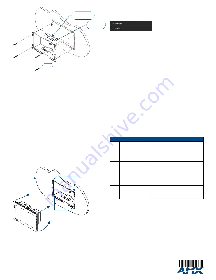
Powering On/Off X Series Panels
Modero X Series touch panels may be powered on by touching and holding the
Sleep
button.
To power off the panel, press and hold the Sleep button, and select
Power Off
on the on-
screen menu (FIG. 6):
Configuration and Programming
X Series touch panels are equipped with a
Settings
menu that provides the ability to
configure various features on the panels.
To access the
Settings
menu, press and hold the Sleep button, and select
Settings
.
Note
: Information on the Settings menu, panel configuration, and programming is provided in
the
Modero X Series Programming Guide
, available at www.amx.com.
Setting the Panel’s Device Number and Device Name
1. In the Settings menu, select
NetLinx
. This opens a password keypad.
2. Enter the panel password into the keypad (the default is
1988
) and select
OK
to access
the
NetLinx
page.
3. Press
Device Number
to open the NetLinx editing window.
4. Enter a unique Device Number assignment for the panel and press
OK
.
5. Enter a unique Device Name assignment for the panel and press
OK
.
Configuring the Panel’s IP Address
These steps configure the panel to communicate with a network; it is still necessary to
connect to the NetLinx Master (see
Connecting to a NetLinx Master
below).
Network Communication via DHCP
1. In the
Ethernet
page, press
DHCP/Static
field to open the
DHCP/Static
window. Note
that
DHCP
is the default setting.
2. Select
Host Name
, enter the new host name
3. Press
OK
to save changes.
Network Communication via Static Address
1. In the
Ethernet
page, press
DHCP/Static
to open the
DHCP/Static
window.
2. Select
Static
to open the
Static IP
window.
3. Press any field to open a keypad or keyboard (depending on the field), and enter the
appropriate network address information.
4. Press
OK
to save your changes and return to the
Ethernet
page.
Connecting to a NetLinx Master
To establish the type of connection to make between the panel and the NetLinx Master:
1. In the
NetLinx
page, press
Mode
to choose the connection mode (
URL
,
Listen
or
Auto
):
2. If password security is enabled on the target Master, enter the Username and
Password:
a. Select
Username
to open the
NetLinx
window.
b. Enter the
Username
and
Password
required by the Master.
c.
Press
OK
to save changes and return to the
NetLinx
page.
Related Software and Additional Documentation (at www.amx.com)
•
Programming the Modero X Series touch panels requires the use of the latest versions
of NetLinx Studio and TPDesign4, both available to download at www.amx.com. Refer
to the NetLinx Studio and TPDesign4 online help for information.
•
For additional information on the MXD-700 panel, refer to the
X-Series Touch Panels
MXD/T-1000, MXD/T-700 & MXD-430 Instruction Manual.
•
For detailed information on the Settings menu as well programming information and
instructions on upgrading firmware, refer to the
Modero X Series Programming Guide
.
FIG. 4
MXD-700 Backbox Installation (Landscape)
FIG. 5
Installing the MXD-700
#4 Screws
2X Installation Clamp
for Wall Thickness
.37 [12.03] to .98 [.25.0]
4X Knock-Outs
Remove for Cable
Routing as Needed
Mounting Surface
Backbox
Latch Hooks
Snaps
FIG. 6
Sleep Button - Press and hold to access Power Off/Settings options
Connection Modes
Mode
Description
Procedures
URL
The device connects to the
target Master’s IP address
via a TCP connection.
1) Select
URL
in the
Mode
menu.
2) Enter the
Master IP/URL
,
Master Port Number
,
and
Username
/
Password
(if required by the
Master).
Press
OK
to save changes.
Listen
This mode allows the panel
to “listen” for the Master’s
communication signals.
Note that in this mode, the
System Number
and
Master
IP/URL
fields are read-only.
1) Select
Listen
in the
Mode
menu.
2) Confirm the panel’s IP address is on the
Master’s URL list (via NetLinx Studio).
3) Press
OK
to save changes.
Note
: The Host Name (set on the Ethernet page),
can be used to locate the panel on the Master
(particularly useful for DHCP connections where
the IP address can change).
Auto
Use this mode when both
the panel and the NetLinx
Master are on the same
Subnet.
1) Select
Auto
in the
Mode
menu.
2) Enter the System Number and Username and
Password (if applicable).
3) Press
OK
to save changes.


