

For full warranty information, refer to the AMX Instruction Manual(s) associated with your Product(s).
10/12
©2012 AMX. All rights reserved. AMX and the AMX logo are registered trademarks of AMX.
AMX reserves the right to alter specifications without notice at any time.
3000 RESEARCH DRIVE, RICHARDSON, TX 75082 • 800.222.0193 • fax 469.624.7153 • technical support 800.932.6993 • www.amx.com
93-5968-10
REV: C
Resetting the MXA-MPL to Factory Defaults
To reset the MXA-MPL to its factory defaults, press and hold the
Factory Reset
button
(FIG. 1) on the front of the device for five seconds.
Configuring the MXA-MPL
Configuring the MXA-MPL into a network requires modification of the device’s corresponding
NetLinx files via NetLinx Studio and the associated touch panel pages via TPDesign 4.
Documentation of the available commands may be found in the
Modero X Series
Programming Guide
, available at
www.amx.com
.
Connecting the MXA-MPL to a Network
Since the MXA-MPL works to transmit HD video and images from an Enova switcher to a
Modero X touch panel, it needs to be connected between the switcher and the touch panel.
To connect the touch panel to the MXA-MPL:
1.
Insert the incoming network connection cable from the Enova switcher to the upper
Ethernet In
RJ-45 connector (FIG. 1).
2.
If the touch panel is not panoramic (MXD/T-1000, MXD/T-700, MXD-430), connect an
outgoing Ethernet cable from the MXA-MPL’s
Ethernet Out
RJ-45 connector to an
AMX-certified high-power Power over Ethernet injector. Do not apply power until the
installation is complete.
3.
If the touch panel is a panoramic model (MXD/T-1900L-PAN or MXD/T-2000XL-PAN),
outgoing power to the touch panel may be supplied via the MXA-MPL’s 2-pin
connector output (FIG. 1) or through another source. Do not apply power until the
installation is complete.
WARNING:
If using the MXA-MPL’s 2-pin connector for power for a touch panel, please refer
to the
MXA-MP/MPL Operation Reference Guide
for maximum cable lengths between the
MXA-MPL and the touch panel, based on cable gauge. Using a separate power source for
panoramic panel installations that require long cable runs is highly recommended.
4.
When the installation is complete, apply power to the MXA-MPL and to the touch
panel. Verify via the LEDs on the front of the device that it is receiving power and is
connected to the network.
5.
If the touch panel has not been configured to receive video signals from the MXA-MPL,
do so now.
NOTE:
For PoE-powered Modero X touch panels, the AMX-certified PoE injector must be
connected between the MXA-MPL and the touch panel. Use of a PoE switch in place of an
AMX-certified PoE injector is NOT recommended.
Configuring the MXA-MPL to Receive Video
NOTE:
For more information on configuring a Modero X touch panel, please refer to the
Modero X Series Programming Guide
, available at
www.amx.com
.
After the MXA-MPL is connected to the network, the touch panel to which it is
connected needs to be configured to receive its signals. To configure the touch panel:
1.
From the
Settings
page, select
Connections & Networks
.
2.
From the
Connections & Networks
page, select
Breakout Box
to open the
Breakout
Box
.
3.
Press the
Breakout Box
button to enable the panel to receive information from
the MXA-MPL.
4.
If the MXA-MPL is connected, the remaining information on the
Breakout Box
page will
self-populate.
NOTE:
If the MXA-MPL is not connected to the touch panel, any attempts at enabling the
panel will fail, and the
Breakout Box
page will be blank other than the
Breakout Box
button.
Rack Mounting the MXA-MPL
The MXA-MPL may be put in a freestanding location, but the device may also be installed in
a standard rack. Installation in a rack requires the use of an MPA-VRK Rack Mounting Tray
(
FG5968-30
) (FIG. 3), available from
www.amx.com
.
To install MXA-MPL devices in a MPA-VRK Rack Mounting Tray:
1.
Select a position on the Rack Mounting Tray for the installation. The Rack Mounting
Tray contains screw holes to allow single or double MXA-MPL
installations.
2.
Using the screws included with the MPA-VRK, install the screws to the bottom of the
MXA-MPL through the Rack Mounting Tray (FIG. 4). Use four screws for each device,
at each corner
.
3.
Connect the Rack Mounting Tray to the rack with the provided bolts.
4.
Connect the MXA-MPL to the network and apply power.
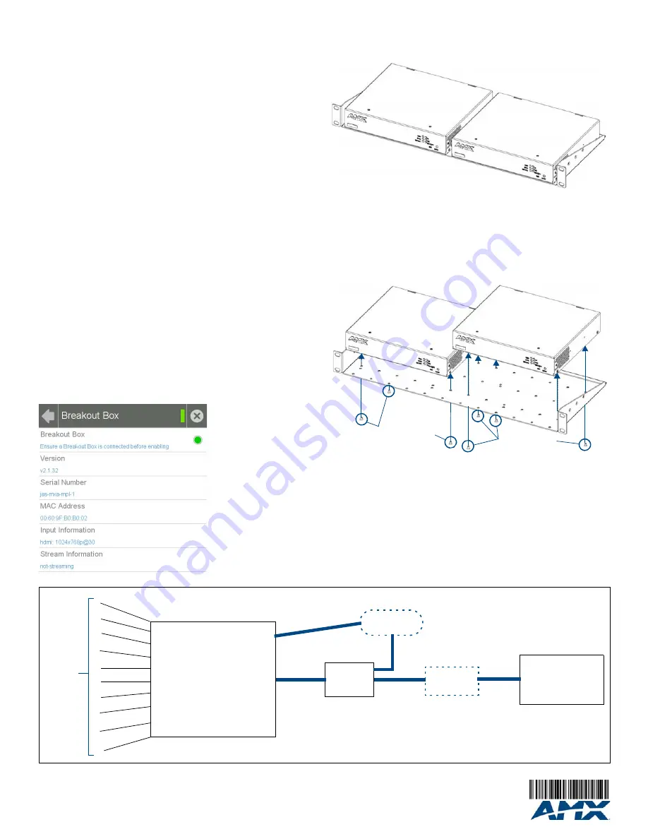
FIG. 2
Breakout Box Settings page
FIG. 3
MPA-VRK Rack Mounting Tray
FIG. 4
Installing two MXA-MPL devices in a Rack Mounting Tray
MXA-MPL
MXA-MPL
Mounting screws
MXA-MPL
MXA-MPL
Mounting screws
AMX-certified
PoEinjector
(if needed)
MXA-MPL
Modero X Touch Panel
1
Enova DVX or DGX
2
3
4
5
6
7
8
9
10
Source
Devices
HDMI
CAT 5
LAN/WAN
MXA-MPL Installation Diagram
LAN


