AMX Corporation reserves the right to alter specifications without notice at any time.
For full warranty information, refer to the AMX Instruction Manual(s) associated with your Product(s).
065-004-2820 5/05 ©2005
AMX Corporation. All rights reserved. The AMX logo is a trademark of AMX Corporation.
3000 RESEARCH DRIVE, RICHARDSON, TX 75082 • 800.222.0193 • fax 469.624.7153 • technical support 800.932.6993 • www.amx.com
93-2178-10
REV: F
•
Beyond this menu, press the TAB button to navigate through the elements on
the pages until an asterisk appears next to the desired selection.
•
Press the spacebar to make a selection (press again to de-select).
Step 4: Add MAX-AVM & MAX-AOM Module(s)
Before you can use either the MAX-AVM or MAX-AOM modules, they must each first
be added to the system, via the
Output Module Setup
options in the MAX Admin
Menu. You should add the modules to the server before making any physical
connections.
Adding MAX-AVM Audio/Video Modules
Complete these steps for each MAX-AVM module that you want to add to the MMS:
1.
In the MAX Admin Menu, select
Output Module Setup > Add Output Module
> AVM
.
2.
In the
Enter Output Number
field, specify the output on the server that you
want to assign to this AVM (range = 1 - 33). Each AVM module requires one
output. Select OK to proceed.
Note
: The server will not allow you to assign a module to an output/zone that is
already in use. Select
Output Module Setup > View
to review the current
output/zone assignments.
3.
In the
Enter Serial Number
field, enter the AVMs’
Setup Serial Number
. This
number is printed on a decal located on the bottom of each AVM enclosure.
4.
A message is displayed to notify you that the AVM module has been added to
the system. Select OK to return to the Output Module Setup menu.
5.
Select OK again to return to the main menu, then select
Restart MAX
daemon
.
Adding a MAX-AOM Audio-Only Module
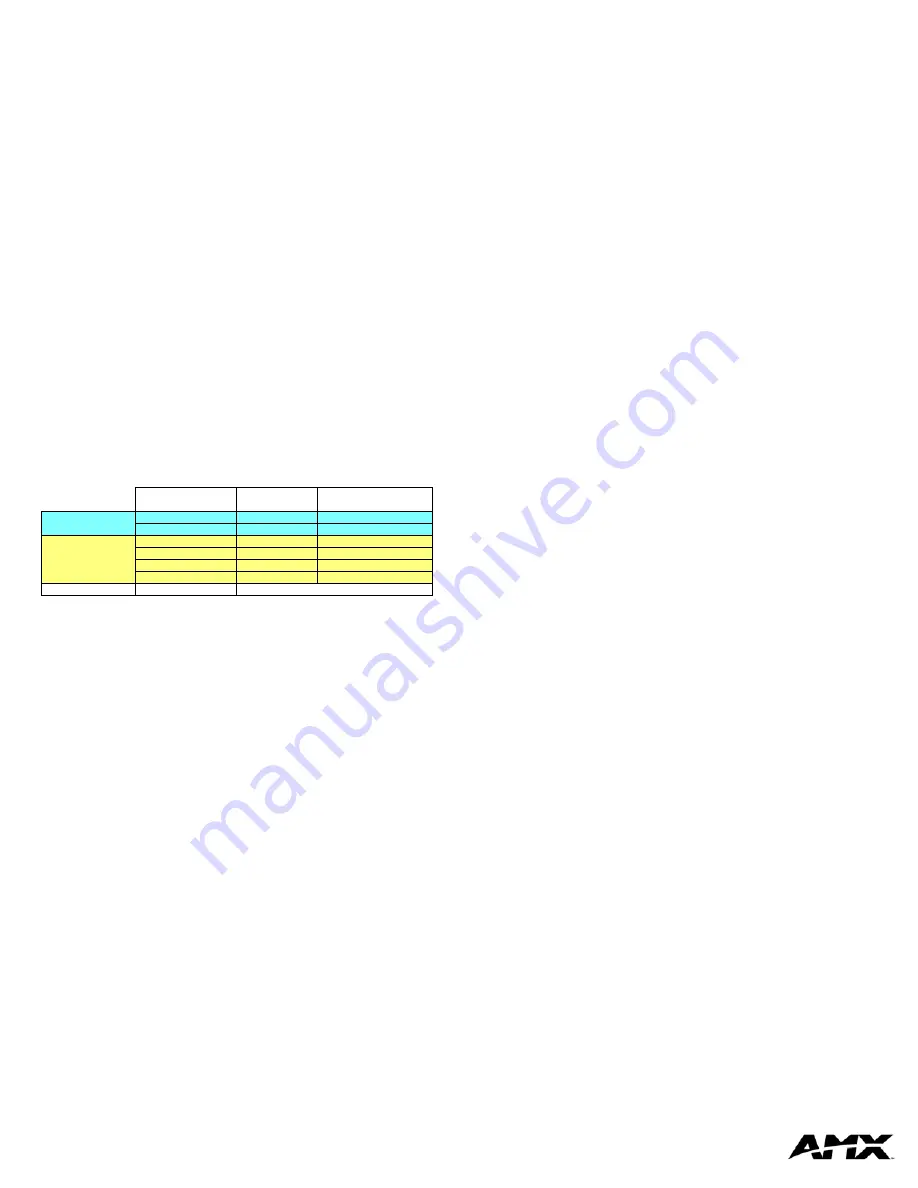
The 2 built-in audio outputs on the MMS-01S (see FIG. 1) utilize the internal
USB 1
port on the server. To add an external AOM module to the MMS-01S server, it is
important to understand that:
•
The two built-in audio outputs occupy audio outputs 1 and 2 on USB 1, leaving
outputs 3 and 4 on USB port 1 open.
•
The USB port on the rear panel of the server which is used to connect an addi-
tional external MAX-AOM module is
USB 2
.
•
When you connect an external AOM module, the four audio outputs on that
AOM will use ports
3
and
4
on
USB 1
(the ports that are unused by the two
built-in audio outputs), and ports
1
and
2
on
USB 2
(as indicated below):
To add a MAX-AOM:
1.
In the MAX Admin Menu, select
Output Module Setup > Add Output Module
> AOM
.
2.
In the
Enter Output Number
field, specify the first of up to 4 outputs on the
server that you want to assign to the AOM (range = 1 - 33). Each AOM requires
up to 4 server outputs to accommodate the 4 audio output/zones provided by
each MAX-AOM. Since the MMS-01S supports one MAX-AOM, you’ll assign
up to 4 server outputs (one at a time). Select OK to proceed.
3.
In the
Enter USB Port Number
field, enter the number of the USB port (1 or 2)
on the MMS server that this MAX-AOM will be physically connected to. Select
OK to proceed.
4.
In the
Enter AOM Output Number
field, specify which audio output/zone on the
MAX-AOM (1 - 4) you are adding to the specified server output. Select OK to
proceed.
5.
A message is displayed to notify you that the AOM module has been added to
the system. Select OK to return to the Output Module Setup menu.
Repeat steps 1 through 5 to assign each of the AOM’s four audio output/zones
to a USB port and output on the MMS server.
Note
: Always assign 4 consecutive server outputs to the MAX-AOM, even if
you don’t plan to use all of the AOM’s outputs right away. Also, assign the 4
server outputs starting either with output #1 (if there are no MAX-AVMs on this
server), or immediately after the last output assigned to an AVM. To avoid
potential confusion later, do not mix AOM outputs and AVM outputs on the
server.
6.
Select
Restart MAX daemon
.
Step 5: Connect the Modules To the MMS Server
Once the MAX-AVM and MAX-AOM modules have been added to the server via the
MAX Admin Menu, you can physically connect them to the MMS server.
Connecting MAX-AVM Modules
Note that multiple AVMs require a GB Ethernet switch (not included).
1.
Connect the audio outputs, using either one of two options:
a. Use the supplied mini-stereo to RCA adapter for analog audio output
b. Use a coaxial cable for digital audio output
2.
Use either a VGA or S-Video cable to connect the video output on the AVM to a
display device.
3.
Use ethernet cables to connect the ethernet port on the AVM to a GB ethernet
switch (not included), and the GB ethernet switch to the A/V OUT connector on
the MMS server.
4.
Connect the included power supply.
5.
Push the power button on the front panel of the AVM, and allow up to one
minute for the module to boot up.
Power up the MMS
before
applying power to the AVM module(s).
Connecting the MAX-AOM Module
Note
: Do not use a USB hub with MMS servers or AOM modules.
1.
Connect the MAX-AOM to an audio system (amplifier, switcher, etc.), using one
of two options:
a. Use RCA cables for analog stereo output (L and R)
b. Use a coaxial cable for digital audio output (D)
2.
Connect the included power supply to apply power to the AOM.
3.
Use the supplied USB cable to connect the AOM module to a USB port on the
MMS server.
Power up the AOM
before
connecting to the MMS server.
Note:
Refer to the MAX-AOM and MAX-AVM Installation Guides (available from
www.amx.com) for detailed product information.
Step 6: Install and Configure WinMAX Software
Once the MAX-AVM and AOM modules have been added and connected to the
MMS server, you can use the WinMAX software application to initiate and control
playback of movies or music.
If its not already installed, load the WinMAX application on your PC. WinMAX can be
downloaded from www.amx.com as a self-extracting executable.
If you intend to connect to the MMS via a LAN connection, verify that the PC is
communicating properly with the network, and that the MMS server is powered and
booted up.
Note
: For WinMAX to be viewed properly, set your PCs resolution to
1024 x 768
.
1.
Use an ethernet cable to connect the ETHERNET CONTROL port on the MMS
server to the LAN that the PC running WinMAX is on.
2.
Launch the WinMAX software on your PC and open the
System Information
tab, where you can specify the network address of the MMS server.
3.
Change the
Server’s IP Address or URL
field to match that of the MMS server
you are connecting to. Click on the disk icon next to the text-entry field to save
this configuration.
If you are connecting to the MMS server via a direct connection with a PC
(using a crossover ethernet cable), be sure that the IP Address of the Network
card in your PC is in the same range as the server, but
not the same as
the
server. For example a network card setting of 192.168.1.31 will work with an IP
address of 192.168.1.30.
The default IP Address for all MAX servers is
192.168.1.30
.
•
The blank fields should fill in momentarily, indicating that the MMS has been
recognized.
If You Don’t Connect
•
Check ethernet cables and verify that all connections are intact.
•
If you are connecting to the server via a PC network, be sure that the
IP
address
and
Subnet Mask
settings are appropriate for your network configura-
tion. Consult your network administrator for help with this.
You can also use WinMAX to establish a Telnet connection with the MMS to access
the MAX Admin Menu: in the WinMAX
System Information
tab, click on
Server
Configuration
. You will be prompted for a
User Name
and
Password
. These are
case sensitive, and by default:
•
User Name =
root
•
Password =
mozart
Note
: If you have connected directly to the MMS (as described in Step 1), you will not
be prompted for a User Name or Password.
Step 7: DVD and CD Playback
Once you have established communication with the MMS server via WinMAX, you
can use WinMAX to initiate and control playback of movies or music.
Note that for DVDs, the region code of the DVD must match the region code setting
on the MMS. By default, MMS servers are set to Region Code 1. Refer to the
DVD
Region Code Settings
insert for details and instructions on changing the Region
Code setting on MMS servers.
Playing a DVD
In WinMAX, open the
Movies
tab. Select the
Output Zone
that is associated with the
AVM that you will use for display, then select a DVD title (MMS servers ship with one
DVD loaded and ready for playback), and click the
Play
button.
Playing a CD
Open the
Music
tab. Select the
Output Zone
that is associated with the AOM that you
will use for playback. Then, select a CD title (MMS servers ship with one CD loaded
and ready for playback), and click the
Play
button.
Note
: Use WinMAX to add/remove content (DVDs/CDs) on the MMS server. Refer to
the WinMAX Instruction Manual for details.
Notice
: MAX Products are not designed or intended to, and may not be used to,
violate anyone’s copyright or other intellectual property rights. Each user of the MAX
Products may only use the Products in connection with materials legally owned or
licensed by such user and only to the extent such ownership or license rights permit
such use.
MMS Output/Zone
(1-33)
USB Port
(1-2)
Audio Output
(1-4)
built-in audio outputs
on MMS
1
1
1
2
1
2
external AOM
3
1
3
4
1
4
5
2
1
6
2
2
MAX-AVM(s)
7...(to 33)
AVM 3...