

For full warranty information, refer to the AMX Instruction Manual(s) associated with your Product(s).
6/14
©2014 AMX. All rights reserved. AMX and the AMX logo are registered trademarks of AMX.
AMX reserves the right to alter specifications without notice at any time.
3000 RESEARCH DRIVE, RICHARDSON, TX 75082 • 800.222.0193 • fax 469.624.7153 • technical support 800.932.6993 • www.amx.com
93-1905-07
REV: A
Mounting the DVX into an Equipment Rack
The DVX occupies three rack units in a standard equipment rack. Install the included
rack mounting brackets using the supplied mounting screws prior to securing the unit in
the rack.
Warning
: The DVX should not be installed in enclosed spaces. ALWAYS ensure that
the rack enclosure is adequately ventilated. Do not block any ventilation openings. It is
recommended that you leave 1 RU of space above the DVX when you install it in a
rack. DO NOT stand other units directly on top of the DVX when it is rack mounted, as
this will place excessive strain on the mounting brackets.
ALWAYS ensure that the rack enclosure is adequately ventilated. Do not block any
ventilation openings. Sufficient airflow must be achieved (by convection or forced-air
cooling) to satisfy the ventilation requirements of all the items of equipment installed
within the rack.
Note:
Connect the LAN port to a LAN with DHCP before powering up the device
.
VIDEO INPUTS
The DVX features 4 connectors which route video from connected source input devices
to the connected output devices.
MULTI-FORMAT VIDEO INPUTS (1-2)
Each MULTI-FORMAT VIDEO INPUT connector supports DVI-D, as well as VGA,
S-Video, Composite, Component, and HDMI inputs, using the appropriate adapter
cables. These ports are HDCP compatible.
Consult the
Enova DVX-2150HD/2155HD/2110HD All-In-One Presentation Switcher
Operation/Reference Guide
for information on adapter cables.
HDMI INPUTS (3-4)
The HDMI INPUT connectors support digital audio in addition to DVI or HDMI digital
video. All HDMI inputs are HDMI (with 3D and Deep Color) and HDCP compatible.
AUDIO INPUTS
The DVX allows independent switching of video and audio. Video and audio inputs of
the same number do not have to be connected to the same source equipment. (The
DVX features 6 audio connectors including the 2 HDMI inputs.)
AUDIO INPUTS (1-2)
The two AUDIO INPUTS connectors receive up to two unbalanced stereo audio inputs.
AUDIO INPUTS (5-6)
The two AUDIO INPUTS connectors can be wired for either balanced (differential) or
unbalanced (single-ended) stereo audio.
AUDIO OUTPUTS (1-3)
The AMP OUT amplified audio output (1) differs according to the DVX model you are
using:
•
-SP models use a 4-position captive wire connector to provide amplified, variable,
mono or stereo audio output.
•
-T models use a two 2-position captive wire connector to provide 70V or 100V
mono amplified audio output. Connect a speaker to either the 70V or 100V
terminal, but not both simultaneously.
The two AUDIO OUTPUT connectors (2-3) provide line level balanced or unbalanced,
mono or stereo line-level audio output.
VIDEO OUTPUTS (1-2)
2 HDMI Output connectors (1-2) provide HDMI video output.
1 DXLink Twisted Pair output (1) mirrors HDMI output 1. It provides digital video, audio,
Ethernet, and bi-directional control over Twisted Pair Cable to DXLink Receivers. All
video outputs are HDCP compatible.
Note:
Use the DXLINK_ETH command to enable Ethernet traffic through DXLINK
outputs. See the Enova DVX-2150HD/2155HD/2110HD All-In-One Presentation
Switcher Operation/Reference Guide for more information on these commands.
PROGRAM Port
The PROGRAM port connects the DVX to a communication port on a PC, and is
intended primarily to be used to configure system settings.
Accessing the Configuration Settings
You can access the configuration settings for the DVX by using the buttons on the front
panel of the unit or by using a web browser.
Using the Front Panel Buttons
You can access the configuration settings for the DVX by using the VIDEO MENU,
AUDIO MENU, SWITCH, and STATUS buttons on the front panel of the DVX. Pressing
any button opens its respective menu on the LCD display on the front panel.
Press the TAKE pushbutton to implement an audio/video switch while you are in the
Switch menu on the LCD display. When in an audio or video menu, press the button to
cycle through audio and video inputs or outputs (depending on the menu.)
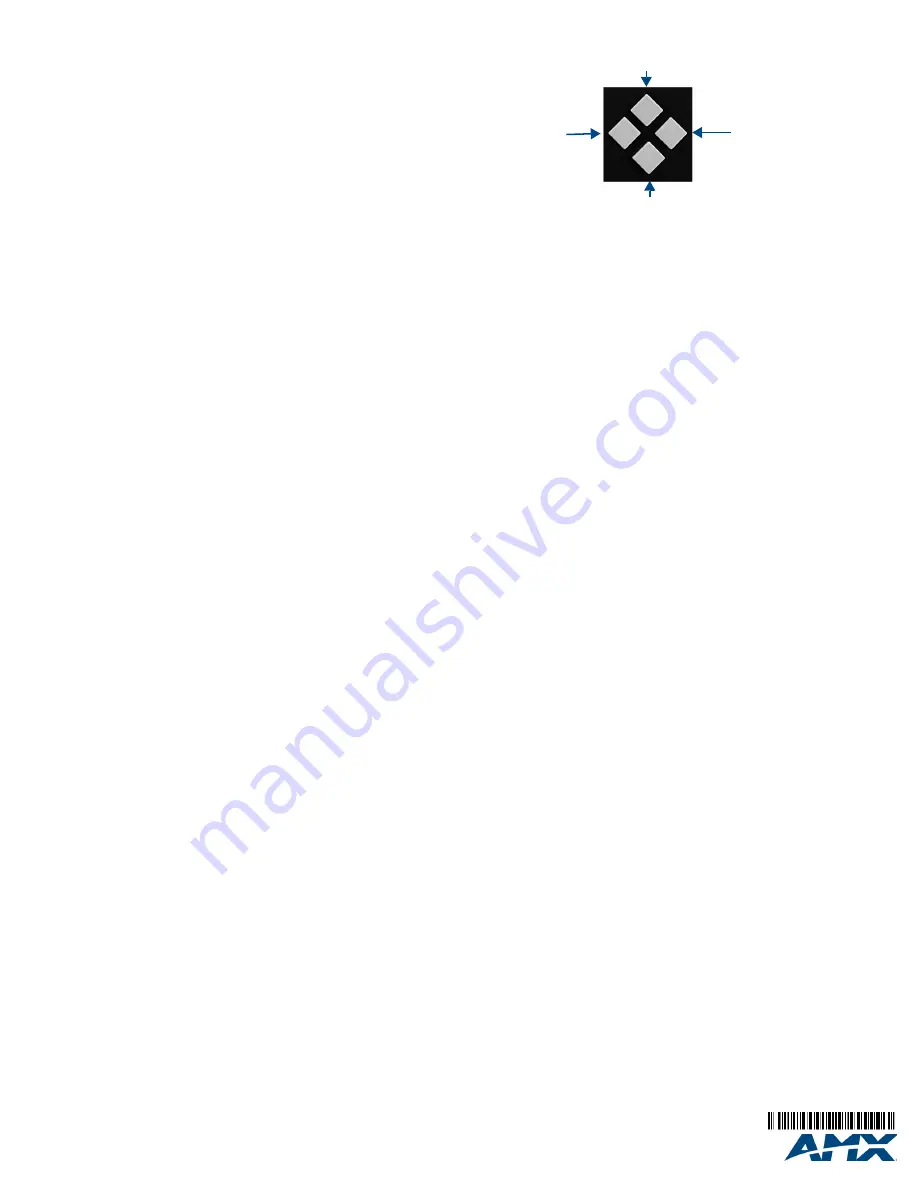
Use the Navigational buttons to traverse the available options and change their values.
FIG. 2 displays the navigational function of each button.
Selecting a Video Test Pattern
Selecting a test pattern for your input source can help determine if you have your video
devices connected correctly. Perform these steps to select a test pattern:
1.
Press the VIDEO MENU button on the front panel of the DVX to open the Video
Output menu.
2.
Press the left and right navigation buttons to select the output on which to display
the test pattern (ALL, 1, or 2). (
Note:
You cannot display a test pattern on the
DXLINK output (1) from the front panel menu. Refer to documentation for the
DXLink receiver for information on displaying a test pattern from the receiver.
)
3.
Press the down navigational button until the Output Test Pattern option appears.
4.
Use the left and right navigational buttons to select an appropriate output test
pattern.
Selecting an Audio Test Tone
Selecting a test tone for your input source can help determine if you have your audio
devices connected correctly. Perform these steps to select a test tone:
1.
Press the AUDIO MENU button on the front panel of the DVX to open the Audio
Output menu.
2.
Press the left and right navigation buttons to select the output on which to play the
test tone (ALL, 1, 2, or 3).
3.
Press the down navigational button until the Test Tone option appears.
4.
Use the left and right navigational buttons to select an appropriate audio test tone.
Setting the Video Type for a Video Input
Each video input type must be set manually. Perform these steps to set the video type
for a video input:
1.
Press the VIDEO MENU button on the front panel of the DVX two times to open
the Video Input menu.
2.
Press the left and right navigation buttons to select the input to change. You can
select any input from 1-4.
3.
Press the down navigational button until the Type option appears.
4.
Use the left and right navigational buttons to select the video format for the
selected input. For Multi-Format inputs, you can choose from HDMI, DVI, VGA,
Component, S-Video, and Composite. The default setting is Component. For
HDMI inputs, you can choose from HDMI or DVI.
Locating the IP Address of the DVX
You can locate the IP address of the DVX by using the buttons on the front panel of the
unit. The IP address appears on the LCD display on the front panel of the switcher.
Perform these steps to locate the IP address of the unit:
1.
Press the STATUS button on the front panel of the unit to open the Status Menu.
The Status options appear on the LCD display.
2.
Use the UP and DOWN navigational arrow buttons to navigate through the
options until you find the switcher’s IP address. Note the IP address for future
reference.
Note:
You can use the Status menu to verify current TCP/IP settings using the UP and
DOWN navigational buttons.
Using a Web Browser
T
he system configuration pages are available by entering the IP address of the NetLinx
master into the location bar of your web browser. Entering your IP address into your
web browser opens the Main WebControl page. Perform these steps to access the
configuration settings:
1.
Open a web browser, and enter the IP address of the DVX in the location bar of
the web browser. The Main WebControl page opens.
Note:
WebControl requires that you install the latest version of the Adobe Flash Player
plug-in for your browser.
If your browser does not have the Flash Player plug-in
installed, you will be prompted to install it.
2.
Use the Device options menu at the top of the screen to select
<DEVICE #> -
DVX-211xHD Switch Device
.
Additional Documentation
For more information, consult the
Enova DVX-2150HD/2155HD/2110HD All-In-One
Presentation Switcher Operation/Reference Guide
available at
www.amx.com
.
FIG. 2
Navigation buttons
Move down to next menu configuration parameter
Move up to previous menu configuration parameter
Decrease value, or
change the state of
the selected parameter
Increase value, or
change the state of
the selected parameter


