


Appendix E - Upgrading/Downgrading the System
262
Enova Digital Media Switchers - Hardware Reference Manual
After the CPU is upgraded to 100 Series, some boards may not power up. This is normal behavior for boards with
firmware that does not match 100 Series compatibility. Upgrade the enclosure to regain full board power up.
Endpoint devices bound to the replaced integrated Master (DGX 8/16/32/64 CPU) via TCP/UDP connection
scheme are not detectable by the new integrated Master (DGX 100 Series CPU) until the new Master is configured
for the IP address used by the previous Master. (NDP devices appear in NetLinx Studio’s OnLine Tree as unbound
devices.)
When a 100 Series system powers up but contains I/O boards with incompatible firmware versions, the CPU will take
longer than normal to boot (15 - 30 min, depending on cage size) and cause the System Status LED to blink red/
green. This indicates that incompatible boards are present and need updating. To shorten the boot time and
avoid the blinking red/green LEDs, the system can be booted with the boards unseated. Then, once the 5002 is
online in about 4 min (indicated by blinking green LED), the boards may be added and upgraded per the normal
kit transfer process.
Items Required
Enova DGX 100 Series replacement CPU board
Phillips #1 screwdriver
ESD wristband and cord with an alligator clip
ESD WARNING: To avoid ESD (Electrostatic Discharge) damage to sensitive components, make sure you are properly grounded
before touching any internal Enova DGX materials. Use an ESD wristband and cord with an alligator clip attached to a good
ground source.
Removing and Replacing an DGX CPU board assembly:
NOTE:
If SC Fiber Boards are in the enclosure, remove them before beginning the following instructions.
1.
Turn off AC power to the enclosure. Make sure none of the power supply LEDs are illuminated.
2.
Disconnect all cables connected to the CPU and power supplies.
3.
Remove the screws from CPU faceplate: seventeen screws in the DGX 64, three screws in DGX 8/16/32 (FIG. 146):
4.
Remove the CPU faceplate and set aside.
5.
Use the removal tab indicated to pull the CPU board assembly straight out of the enclosure (FIG. 147):
6.
Place the old CPU board in an ESD approved static shield bag and set aside.
7.
Slowly slide the replacement CPU board into the empty slot, being careful to align the edges in the board guides
along the insides of the slot (FIG. 148):
FIG. 146
Remove screws that hold faceplate
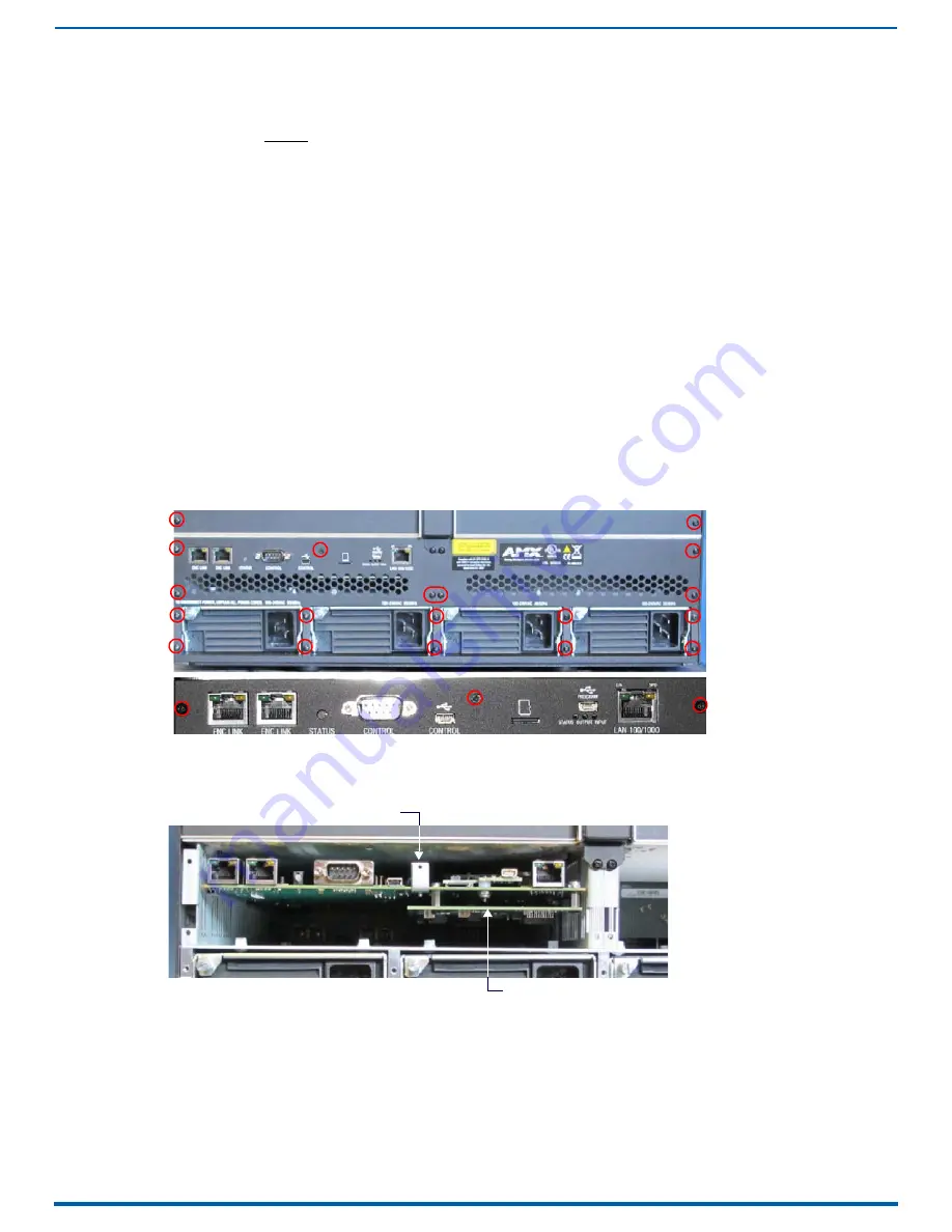
FIG. 147
Use removal tab to pull CPU straight out
Removal tab
Daughter card (DGX-64 only)


