Installation
4
AXP-CCS/AXM-CCS Softwire Camera Center
Verifying the AXP-AI8 I/O DIP Switch Settings
The AXP-AI8 contains an 8-position DIP switch that is factory-set with positions 1 - 6 OFF (up) to
enable joystick and speed control operation. Verify that the DIP switch settings on the AXP-CCS
and AXM-CCS match the settings shown in the DIP Swich Positions and Values table. Refer to
the
Setting the AXlink Device Numbers
section on page 3 to access the AXP-AI8 board.
Mounting the AXP-CCS
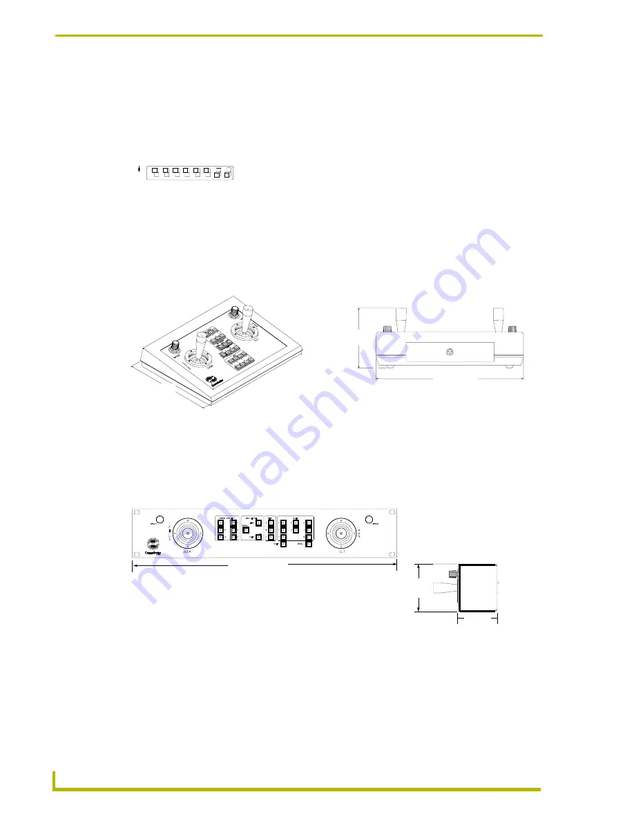
The AXP-CCS is a table-top configuration, and can be mounted on any flat surface. FIG. 4 shows
the dimensions of the AXP-CCS.
Mounting the AXM-CCS
The AXM-CCS can be mounted in most types of electronic equipment racks. FIG. 5 the AXM-
CCS dimensions.
1.
Insert the AXM-CCS into the equipment rack.
2.
Line up the top left and bottom-right screw holes and start the #10-32 screws.
3.
Starting with the bottom-left and top-right screws, tighten all the screws.
FIG. 3
I/O DIP switch settings
FIG. 4
AXP-CCS dimensions
FIG. 5
AXM-CCS dimensions
1 2 3 4 5 6 7 8
The DIP switch must be set according
to this example for proper operation.
ON
4.00"
(10.60 cm)
10.00"
(25.40 cm)
8.03"
(20.40 cm)
19.00"
(48.26 cm)
3.47"
(8.81 cm)
2.75"
(6.99 cm)
Front view
Side view
Summary of Contents for AXM-CCS
Page 1: ...instruction manual Camera Control Systems AXP CCS AXM CCS Softwire Camera Centers ...
Page 4: ...ii AXP CCS AXM CCS Softwire Camera Centers Table of Contents ...
Page 6: ...Product Information 2 AXP CCS AXM CCS Softwire Camera Centers ...
Page 13: ...Programming 9 AXP CCS AXM CCS Softwire Camera Centers ...


