


Specifications Information and Repair Parts Manual
316F-95 and 316F-99
316F-251-00
1
10/2016
Please read and save this Repair Parts Manual. Read this manual and the General Operating Instructions carefully before attempting to assemble,
install, operate or maintain the product described. Protect yourself and others by observing all safety information. The Safety Instructions are contained
in the General Operating Instructions. Failure to comply with the safety instructions accompanying this product could result in personal injury and/or
property damage! Retain instructions for future reference
.
AMT reserves the right to discontinue any model or change specifications at any time without
incurring any obligation.
©2016 AMT Pump Company, A Subsidiary of The Gorman-Rupp Company, All Rights Reserved.
Periodic maintenance and inspection is required on all pumps to ensure proper operation. Unit must be clear of debris and sediment. Inspect for leaks and loose bolts. Failure
to do so voids warranty.
2-Inch Self-Priming Dredging Pump
Refer to pump manual 1808-633-00 (engine-driven) or 1808-635-00 (pedestal mount) for General Operating and Safety Instructions.
DESCRIPTION
These dredging pumps are abrasion-resistant, heavy duty, centrifugal, self-priming (to 20 ft. lift), portable units shipped completely assembled and
mounted. Pump is equipped with abrasion resistant high chromium steel, semi-open, solids handling impeller, replaceable volute and wearplate. A built-
in check valve assists in priming and a silicon-carbide mechanical shaft seal resists wear and leaking. Simple four bolt casing design for easy cleanout
and wear part replacement. Handles liquids from 40º to 160º F (4º to 71º C). This pump is for use with nonflammable liquids compatible with pump
component materials.
MAINTENANCE
Make certain that unit is disconnected from power source before
attempting to service or remove any components!
CLEANING
This unit has been designed to pump seawater laden with (up to 25%)
abrasive particles like sand, stones and shell fragments. It requires
some special periodic maintenance to ensure maximum service life.
1.
After each use pump must be thoroughly flushed and rinsed
with fresh water to remove residual seawater.
2.
When not in use, pump should be stored away from
damaging effects of seawater environment.
This unit has been designed with a removable volute enabling pump to
be cleaned or unclogged easily. Remove casing and volute as
described under MECHANICAL SEAL REPLACEMENT. Remove any
debris found inside of unit. After each use in a seawater environment,
inside and outside of pump must be flushed with fresh water to remove
any seawater residue.
MECHANICAL SEAL REPLACMENT
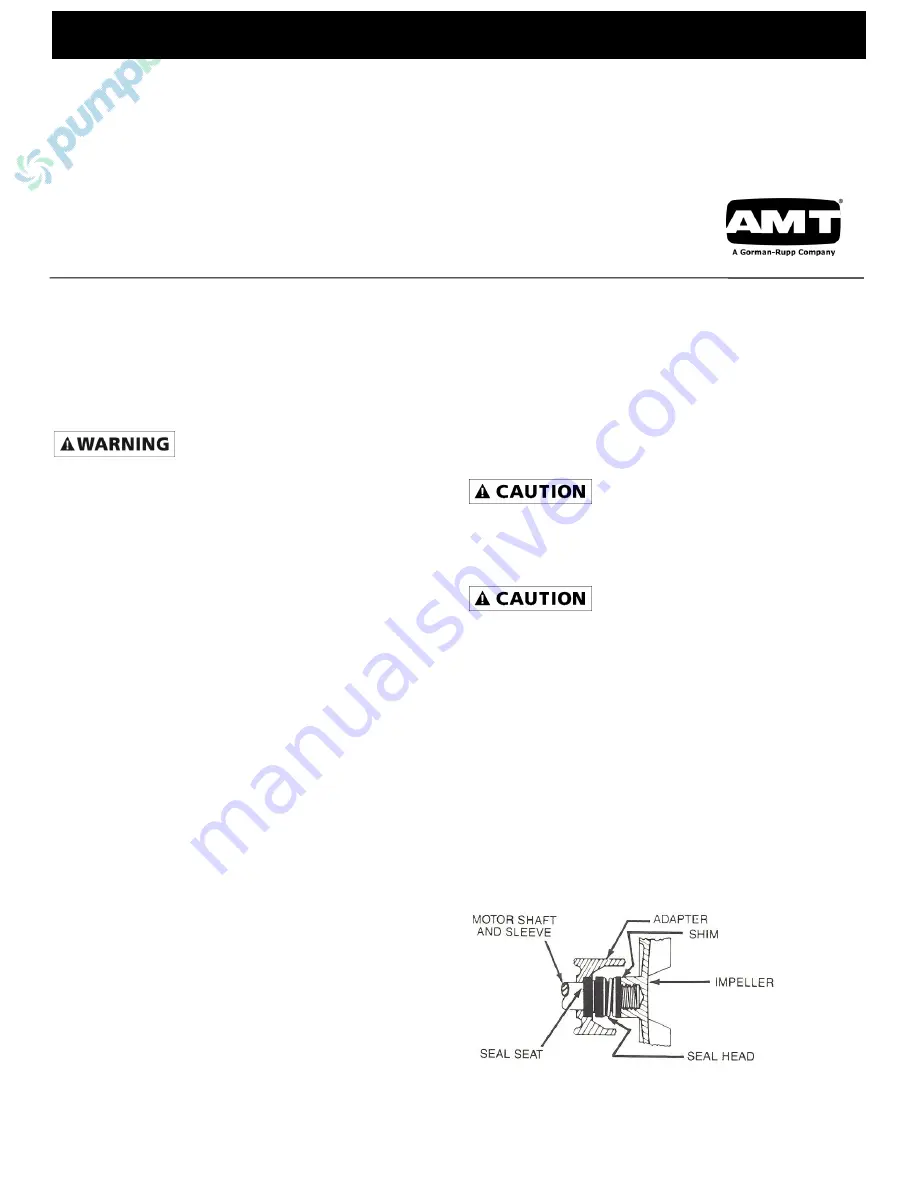
Refer to figures 1 and 2.
NOTE:
Always replace seal seat, (Ref. No. 6), seal head (Ref. No. 7),
and shaft sleeve (Ref. No. 8) to ensure proper mating of mechanical
seal components!
1.
Unthread fasteners (Ref. No. 15) and remove casing (Ref.
No. 13), O-ring (Ref. No. 5) and flapper valve (Ref. No. 12)
from adapter (Ref. No. 3).
2.
Unthread fasteners (Ref. No. 16) and remove volute (Ref.
No. 11) from adapter.
3.
Unscrew impeller (Ref. No. 10) from shaft. Use a rubber
mallet or soft block of wood to loosen impeller. Turn it
counterclockwise. Remove impeller shim(s) (Ref. No. 9),
shaft sleeve and seal head from shaft. Remove wear-plate
(Ref. No. 4) from adapter.
NOTE:
To keep shaft from turning on engine driven units, remove
shroud from engine and hold flywheel in place.
4.
Unthread fasteners (Ref. No. 2 or 32 & 34) and remove
adapter from mounting face.
5.
Push seal seat from adapter recess with a screwdriver.
6.
Clean adapter recess before inserting a new seal seat.
7.
Carefully wipe seal face of new seal seat with a clean cloth.
8.
Wet outside of rubber portion of seal seat with a light coating
of
soapy water.
9.
Press new seal seat squarely into cavity in adapter. Use
finger pressure only to avoid scratching seal seat. (This is a
lapped surface and must be handled very carefully.)
10.
After seal seat is in place, be sure that it is clean and has
not been marred.
11.
Using a clean cloth, wipe shaft and make certain that it is
perfectly clean.
12.
Secure adapter on mounting face.
Tighten fasteners EVENLY to avoid cocking rabbet on mounting
face.
13.
Apply a light coating of soapy water to inside rubber portion
of seal head and slide onto shaft sleeve. Slip shaft sleeve
with seal head onto shaft with sealing face toward polished
sealing surface of seal seat.
Do not touch or wipe sealing face of seal head.
14.
Replace any impeller shim(s) removed in disassembly.
15.
Screw impeller back in place, tightening until it is seated
against shims and shaft sleeve.
16.
Install wearplate into rabbet in
Specifications Information
and Repair Parts Manual adapter aligning fastener holes in
adapter with clearance holes in wearplate. Remount volute
with fasteners.
NOTE:
Do not over tighten fasteners. Fasteners should be snug to
eliminate play between adapter, wearplate, and volute. Pressure
developed from mounting casing to adapter will fix volute and
wearplate into position.
17.
Refer to section entitled SHIM ADJUSTMENT at this time if
shaft sleeve or any other parts listed therein have been
replaced.
18.
Inspect position of flapper valve to ensure proper movement
and seating.
19.
Position O-ring on volute.
NOTE:
Always inspect O-ring seal. Replace when cracked or worn.
Wet O-ring with soapy water for ease of assembly.
20.
Remount casing.
Figure 1
– Mechanical Seal


