The 620A-4 Tester measurement circuitry is
also failsafe current limited, even under worst
case component failure.
A simple startup test
procedure which also has the 620A-4 Tester
user perform a functional check using a
milliammeter would also detect any current
level even getting close to the Failsafe level.
For the 620A-4 Tester the normal or typical
operating current level is less than 5 mA, and
<8mA on most 20 ohm range versions as a
Failsafe Level
.
E-7. Ultra-Safe Power Supply Scheme
The +5 volt power supply is provided directly
by the batteries (for driving the LED displays
and digital logic). The ±5VD is used for driving
IC8, the low battery detection circuit. The ±15V
power supply is generated by IC7 for the digital
voltmeter (DVM) chip set (IC1 and IC2).
The ±5 VA is developed by one DC to DC
convertor circuitry: composed of Q103, Q104,
T102, D103, D104, IC102 for the negative
polarity. The other DC/DC convertor is
composed is composed of Q101, Q102, T101,
D101, D102 and IC101 for the positive polarity.
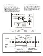
Figure E-3 Constant Current Circuit
I Lo
RL
I hi
RANGE
ATTENUATION
RESISTOR
R215
100K
R221
100K
R222
100K
IC202
IC201
R212
100K
R213
100K


