


Document Part No.
551291 Revision B
Operating Manual
MH Series - Temposonics
®
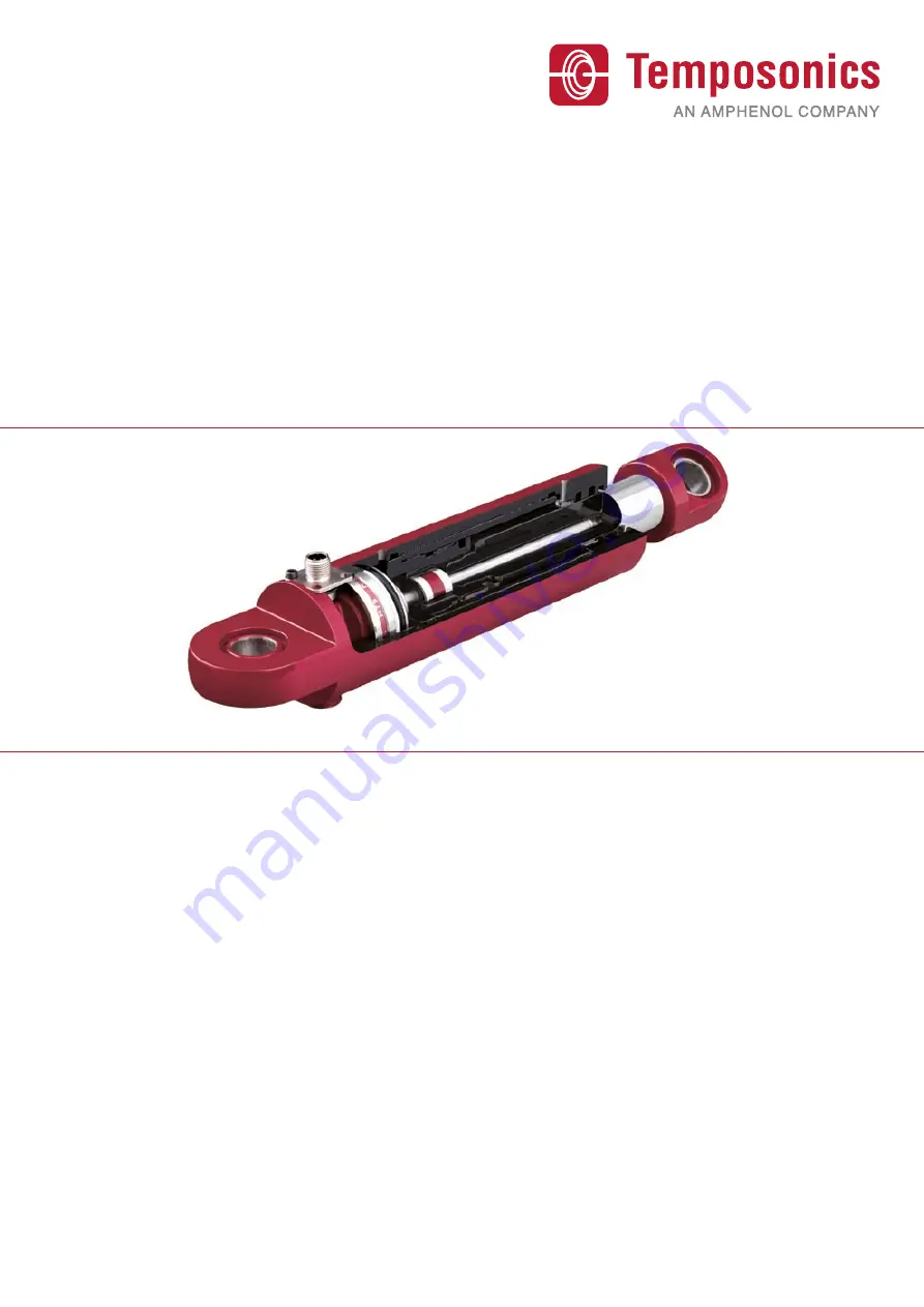
MH Digital
CANopen, CANopen Safety, SAE J1939
Magnetostrictive Linear Position Sensors
Temposonics
®
Document Part Number
551291 Revision B
Absolute, Non-Contact Position Sensors
Operating Manual
MH Series
Temposonics
®
MH Digital
CANopen, CANopen Safety, SAE J1939
All specifications are subject to change. Contact MTS for specifications and engineering
drawings that are critical to your application. Drawings contained in this document are for
reference only.
Please visit www.mtssensor.com for the actual support documentation- related to your
selected model.