IMAC2B009 V2
Uncontrolled Copy - Refer to Ampcontrol Website for Latest Version
Page 20 of 53
Ampcontrol Pty Ltd
– ABN 28 000 915 542
iMAC System User Manual
iMAC2B009 V4
– 10/18
A
P
P
R
OV
E
D
FOR
E
X
T
E
R
N
A
L
D
IS
TR
IB
U
T
ION
–
P
R
OP
E
R
T
Y
OF
A
M
P
C
ON
TR
OL
P
T
Y
LTD
–
N
O
T
T
O
B
E
R
E
P
R
OD
U
C
E
D
I
N
P
A
R
T
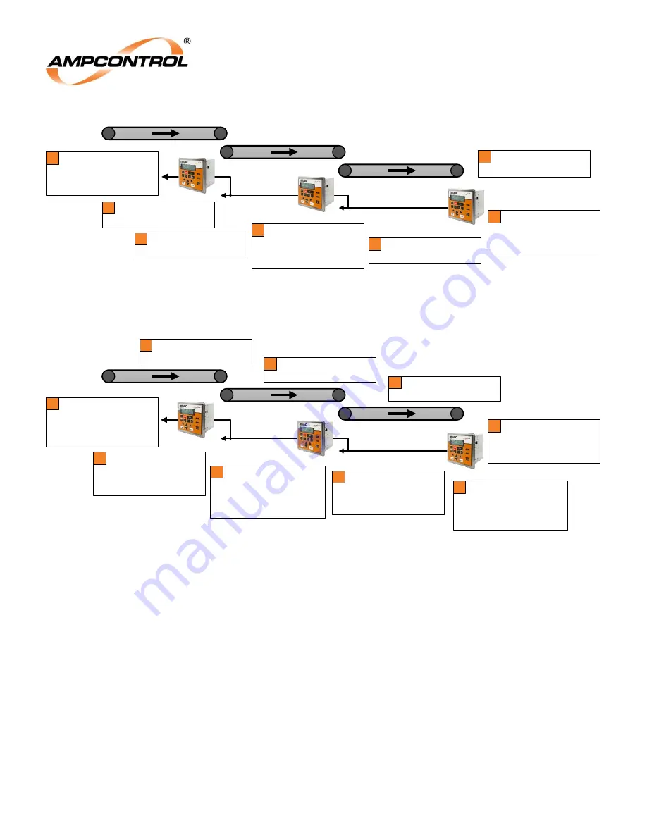
Figure 4.3: Example of the use of Upstream Sequence Bits for Conveyor Sequence Control
Figure 4.4: Example of the use of Downstream Sequence Bits for Conveyor Sequence Control
Conveyor 3
Conveyor 2
Conveyor 1
L1
L1
L1
L2
L2
A SQM module connected to
Controller 3's L1 fieldbus
transmits the L1 Sequence Up
Bit when the SQM’s Reverse
Sequence Input is closed.
1
Controller 1 receives the Up bit
transmitted by Controller 2 on
it L1 fieldbus port. This bit is
stored in Controller 1 as the L1
Sequence Up Bit.
6
Controller 3 receives the L1
Sequence Up Bit on its L1
fieldbus port.
2
Controller 3 transmits the L2
Sequence Up Bit on its L2
fieldbus port.
3
Controller 2 receives the Up bit
transmitted by Controller 3 on
it L1 fieldbus port. This bit is
stored in Controller 2 as the L1
Sequence Up Bit.
4
Controller 2 transmits the L2
Sequence Up Bit on its L2
fieldbus port.
5
Controller 1 initiates a
sequenced conveyor start
7
Controller 3
Controller 2
Controller 1
Conveyor 3
Conveyor 2
Conveyor 1
L1
L1
L1
L2
L2
Controller 1 initiates Conveyor
1 start by closing the CR
(if the system is healthy)
2
Controller 1 receives input
indicating that the speed of
Conveyor 1 has exceeded the
required threshold and
transmits the L1 Sequence
Down Bit on the L1 fieldbus port
3
Controller 2 receives the Down
bit transmitted by Controller 1
on it L2 fieldbus port. This bit is
stored in Controller 2 as the L2
Sequence Down Bit.
4
Controller 2 initiates Conveyor
2 start by closing the CR
(if the system is healthy)
5
Controller 3 receives the Down
bit transmitted by Controller 2
on it L2 fieldbus port. This bit is
stored in Controller 3 as the L2
Sequence Down Bit.
7
Controller 3 receives input
indicating that the speed of the
Conveyor 3 has exceeded the
required threshold and
indicates that the sequenced
start is complete.
9
Controller 3 initiates Conveyor
3 start by closing the CR
(if the system is healthy)
8
Controller 1 receives a request
for a sequenced conveyor start
via L1 Sequence Up Bit or one
of Controller 1's general
purpose inputs
1
Controller 2 receives input
indicating that the speed of
Conveyor 2 has exceeded the
required threshold and
transmits the L1 Sequence
Down Bit on the L1 fieldbus port
6
Controller 3
Controller 2
Controller 1


