


IntesisBox
®
Modbus Server – Mitsubishi Heavy Industries AC
User’s Manual r1.0 eng
© Intesis Software S.L. - All rights reserved
This information is subject to change without notice
IntesisBox
®
is a registered trademark of Intesis Software SL
URL
Email
tel
http://www.intesis.com
[email protected]
+34 938047134
26 / 26
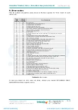
Error codes
9.
This list contains all possible values shown in Modbus registers for
“Error Code” for each
indoor unit.
Error
Code
Modbus
Error in
Remote
Controller
Error Description
0
N/A
No active error
1
E1
Remote controller communication error
2
E2
Duplicated indoor unit address
3
E3
Outdoor unit signal line error
5
E5
Communication error during operation
6
E6
Indoor heat exchanger temperature thermistor anomaly
7
E7
Indoor return air temperature thermistor anomaly
8
E8
Heating overload operation
9
E9
Drain trouble
10
E10
Excessive number of indoor units (more than 17) by controlling one remote
controller
12
E12
Address setting error by mixed setting method
14
E14
Communication error between master and slave indoor units
16
E16
Indoor fan motor anomaly
19
E19
Indoor unit operation check, drain motor check setting error
28
E28
Remote controller temperature thermistor anomaly
30
E30
Unmatched connection of indoor and outdoor unit
31
E31
Duplicated outdoor unit address No.
32
E32
Open L3 Phase on power supply at primary side
33
E33
Inverter primary current error
35
E35
Cooling overload operation
36
E36
Discharge pipe temperature error
37
E37
Outdoor heat exchanger temperature thermistor anomaly
38
E38
Outdoor/Ambient air temperature thermistor anomaly
39
E39
Discharge pipe temperature thermistor anomaly
40
E40
High pressure error
41
E41
Power transistor overheat
42
E42
Current cut
43
E43
Excessive number of indoor units connected, excessive total capacity of connection
45
E45
Communication error between inverter PCB and outdoor control PCB
46
E46
Mixed address setting methods coexistent in same network
47
E47
Inverter over-current error
48
E48
Outdoor DC fan motor anomaly
49
E49
Low pressure anomaly
51
E51
Inverter anomaly
53
E53
Suction pipe temperature thermistor anomaly
54
E54
High/Low pressure sensor anomaly
55
E55
Underneath temperature thermistor anomaly
56
E56
Power transistor temperature thermistor anomaly
57
E57
Insufficient in refrigerant amount or detection of service valve closure
58
E58
Anomalous compressor by loss of synchronism
59
E59
Compressor startup failure
60
E60
Rotor position detection failure / Anomalous compressor rotor lock
61
E61
Communication error between the master unit and slave units
63
E63
Emergency stop
Table 9.1
Error codes
In case you detect an error code not listed, contact your nearest MITSUBISHI HEAVY
INDUSTRIES technical support service.
AMP Air Conditioning
www.ampair.co.uk | [email protected]


