38
AMPW 400-1000L I&O Manual
. Water Piping
(continued)
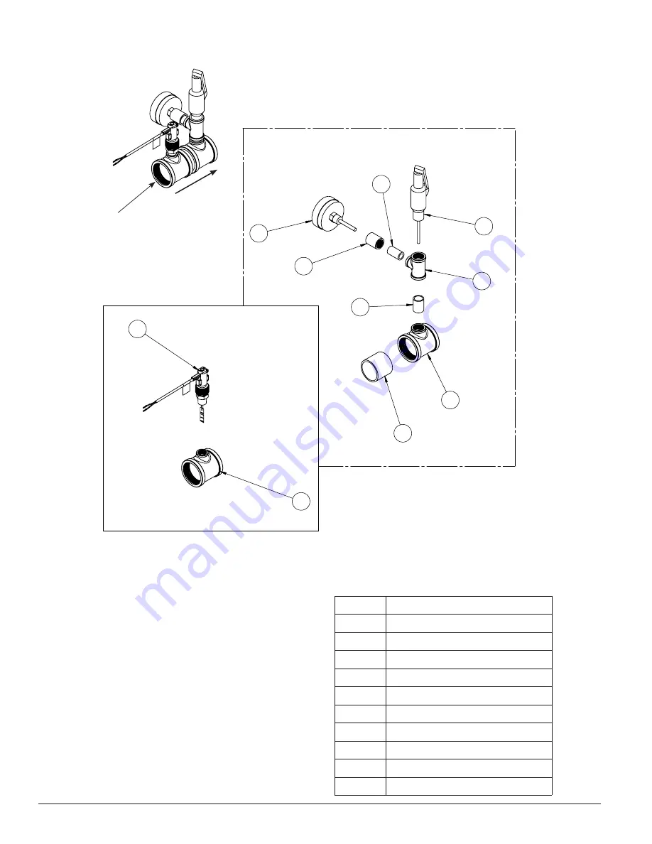
Figure 16: Hot Water Outlet Manifold
B. Factory Supplied Outlet Manifold
1. Some outlet water piping ships loose with the
appliance. These parts must be installed to the
outlet as shown in
Item no.
Description
1
2" X 2" X 1/2" reducing tee
2
2" pipe nipple, close
3
2" X 2" X 3/4" reducing tee
4
3/4" pipe nipple, close
5
3/4" X 1/2" reducing tee
6
T&P relief valve
7
1/2" pipe nipple x 1-1/2" Long
8
1/2" full coupling
9
T&P gauge
10
Water flow switch
Table 17: Outlet Piping Parts
1
10
2
9
3
4
5
8
7
6
Factory Installed
Field Installed
Outside Jacket Water Tri, LAMP 400-1000
ITEM
NO. QTY.
TS Part#
Part Description
Drawing#
1
1
110518-01
2" X 2" X 1/2" reducing Tee, brass, LF
2
1
806600412
2" Pipe Nipple close Sch. 40, brass, LF
N/A
3
1
110518-02
2" X 2" X 3/4" reducing Tee, brass
4
1
94171.9
3/4" Pipe Nipple, Close, Sch. 40, 304 ss
N/A
5
1
110519-01
3/4" X 1/2" reducing Tee, 304 ss
6
1
109297-01
T&P Relief Valve, 3/4" Male, Conbraco 18C-511
7
1
110519-02
1/2" Pipe Nipple x 1-1/2" Long, 304 SS
N/A
8
1
110519-03
1/2" full coupling, 1000# 304 ss
9
1
103470-03
Gauge, Temp/Press, Dial, 1/2" NPT, 3" Dia. 0-250
PSI, 70-320F, Winters# TTD407
N/A
10
1
108396-02
Water Flow Switch With 1/2" NPT brass, Sika#
VK306
N/A
1
Appliance Connection
Flow


