Ammann ASC 70 Operating Manual Download Page 119

 115

ASC 70

396203B

396222

396246

396247


MAINTENANCE MANUAL

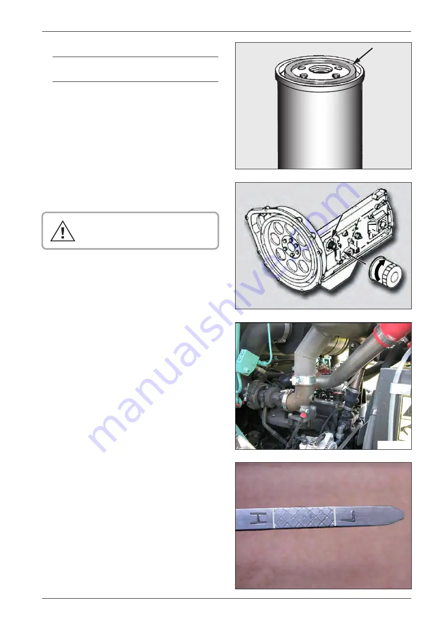
•  Clean the contact surface for filter gasket. Install the filter 

and tighten properly with your hand. 

Do NOT overtighten the filter, its thread 

and gasket may get damaged.

•  Use filler neck to fill the engine.

•  Fill oil to the upper division line of H dipstick. The oil filling 

is of 7 l (7.4 qt). The amount between division lines L and H 

is 1,5 l (1.6 qt).

•  Spread oil over the gasket of new filter.

Engine oil filter 

Order number: 4-9501000307

Summary of Contents for ASC 70

Page 1: ...ASC 70 OPERATING MANUAL SINGLE DRUM ROLLER CUMMINS Tier 3 EDITION 10 2018 EN From Serial No 2742519...

Page 2: ......

Page 3: ...lleistungspegel LWA 106 dB M sto a datum vyd n Place and date of issue Ort und Datum der Ausgabe Nov M sto nad Metuj Jm no Name Name Bc Martin e ovsk Funkce Grade Stelle Quality Control Manager Podpis...

Page 4: ...iv ASC 70...

Page 5: ...of I Specification manual II Operating instructions III Maintenance manual The following explanations serve to familiarise the machinist operator with the roller and to support him during handling an...

Page 6: ...ns of figures are reserved All dimensions and weights are approximate and therefore not binding Ammann Czech Republic a s reserves the right to perform modifications without obligation to inform the m...

Page 7: ...s of the machine moving forward SYMBOLS OF THE SAFETY NOTICES The notice warns of a serious risk of personal injury or other personal hazards The notice warns of possible damages to the machine or its...

Page 8: ...4 ASC 70 Content Content 4 1 SPECIFICATION MANUAL 9 1 1 Basic specification 10 1 2 Dimensional diagram of the Machine 12 1 3 Specifications 14...

Page 9: ...machine 36 2 4 Machine disposal following its life cycle end 37 2 5 Machine description 38 2 6 Actuators and dashboard instruments 39 2 6 1 Power View control 54 2 7 Machine control and use 64 2 7 1...

Page 10: ...ion and service plan 106 3 6 Lubrication and Maintenance 107 Every 20 hours of operation daily 108 3 6 1 Engine oil level check 108 3 6 2 Engine cooling liquid level check 109 3 6 3 Hydraulic oil leve...

Page 11: ...adjustment 138 3 6 28 Oil in the vibrator change 138 3 6 29 Air conditioning system cleaning 139 3 6 30 Hydraulic oil and filter change 140 3 6 31 Suction strainer unit cleaning 144 3 6 32 Engine cool...

Page 12: ...8 ASC 70...

Page 13: ...9 ASC 70 SPECIFICATION MANUAL 1 SPECIFICATION MANUAL ASC 70 Cummins Tier 3...

Page 14: ...be used for compaction by means of stabilisation ASC 70 PD roller with a padfoot drum synchronous kneading and vibrating effect is suitable for the compaction of clay soils up to a layer thickness aft...

Page 15: ...on and safety is identified with a name plate with CE marking 1 Name always mentioned only in the English version 2 Type 3 Serial number 4 Operating weight 5 Maximum weight 6 Rated power 7 Version 8 S...

Page 16: ...L L1 T W W1 W2 ASC 70 D 2560 1300 385 350 2870 2280 5195 25 1680 1875 100 8 51 2 15 2 13 8 113 0 89 8 204 5 1 0 66 1 73 8 ASC 70 PD 2560 1240 1400 385 350 2870 2280 5195 15 1680 1875 100 8 48 8 55 1...

Page 17: ...195 25 1680 1875 100 8 51 2 15 2 13 8 113 0 89 8 204 5 1 0 66 1 73 8 ASC 70 PD 2560 1240 1400 385 350 2870 2280 5195 15 1680 1875 100 8 48 8 55 1 15 2 13 8 113 0 89 8 204 5 0 6 66 1 73 8 ASC 70 PDB 25...

Page 18: ...n ROPS kg lb 140 310 140 310 140 310 140 310 Weight of canopy kg lb 60 130 60 130 60 130 60 130 Weight of canopy posts version without ROPS kg lb 60 130 60 130 60 130 60 130 Weight of blade kg lb 500...

Page 19: ...21 8 0 15 21 8 0 15 21 8 0 15 21 8 Pattern of tyres UK 5 Diamond UK 5 Diamond TD 02 Tractor TD 02 Tractor Number of tyres 2 2 2 2 Number of rear wheels 2 2 2 2 Size of tyres 14 9x24 14 9x24 14 9x24 14...

Page 20: ...US 2 75 0 73 2 75 0 73 2 75 0 73 2 75 0 73 Wiring Voltage V 24 24 24 24 Battery capacity Ah 2x61 2x61 2x61 2x61 Noise and vibration emissions Measured sound power level A LpA at the operator s positi...

Page 21: ...tyre Blade Plates made of Hardox on PD segments Tractor tyre as standard with HX and PD versions Ballasting of tyres with liquid of up to 0 C Ballasting of tyres with liquid of up to 25 C as standard...

Page 22: ...18 ASC 70 Notes...

Page 23: ...19 ASC 70 OPERATION MANUAL 2 OPERATION MANUAL ASC 70 Cummins Tier 3...

Page 24: ...20 ASC 70...

Page 25: ...who will carry out earth work familiar with these conditions He must specify Code of Practice C O P part of which is work procedure for a given work operation and this work procedure will specify int...

Page 26: ...ified in the operation manual of the machine He must ensure that Operation manual of the machine and operational book are kept on specified place to be at dispos al for the driver all the time He must...

Page 27: ...can make no registrations changes or corre ctions in the licence card He she is liable to promptly report his her licence loss to the authority that issued this licence Driving the Roller alone may b...

Page 28: ...ior turning on the engine the controls have to be in their zero position no persons may stay within dangerous reach of the Machine Indicate each Machine startup via an acoustic or light signal and thi...

Page 29: ...stance from buildings or facilities and equipment within which the risk of them be ing damaged due to vibration transfer impact would occur To operate the Machine unless driver control stand fixed pr...

Page 30: ...26 ASC 70 18 4 3 7 13 10 2 5 15 A 14 19 16 20 13 8 11 9 12 17 1 8 6 396340 20 2 1 Major Safety Precautions 2 1 5 Safety inscriptions and signs used on the Machine...

Page 31: ...ry imminent risk of cutting oneself and or chipping off Do NOT touch rotating parts if the engine is running Sym bol located on LH side of the cooler 4 Cooling liquid imminent risk of scald Do NOT ope...

Page 32: ...sten the seat belt before starting to move the Machine Symbol located on LH side of actuator panel 10 Danger of explosion Imminent danger of explosion while handling the battery read Operation Manual...

Page 33: ...lternator Before welding please disconnect alternator and elec tronics of the Machine engine actuator unit Symbol lo cated from within on lateral LH door 16 Ear protectors Use ear muffs when the Machi...

Page 34: ...H win dow 20 Rigging points Sling the Machine in these points only The maximum permitted force for fastening the machine to a vehicle us ing rear slings is 5 t Symbols located along both sides of the...

Page 35: ...m in the Operator di rection second arm akimbo Attention Both arms horizontally sideways raised palms facing forward Attention Danger Oscillating motion of both arms with antebrachium from the positio...

Page 36: ...rt oscillating motions of antebrachium towards the body and back Slow driving backward away from me Both arms stretched upward abreast bent with palms away from the body short oscillating motions of a...

Page 37: ...oth arms lifted forward bent Mark distance X between palms then follows the motion signal Engine start Circular motion of antebrachium of right hand with tight fist Engine cut off Oscillating motion o...

Page 38: ...rly marked packages Admit no storage of these materials in unidentified bottles or other vessels with regard to the risk of being interchanged Especially hazardous is the potential of interchanging fo...

Page 39: ...heck their condition and store in cold dry room recharge the batteries on regular basis Bottom the drum frame up so the damping system has mi nimal sag Protect rubber elements with paint using special...

Page 40: ...that no parts are missing Inform shipper about any deficiencies Before restoration of the Machine service please dewax and wash the preservation agents away with high pressure stream of hot water add...

Page 41: ...onmental policy acts We therefore recommend to always contact Specialized companies with relevant authorization to deal with these operations Machine Manufacturer or Manufacturer appointed accredi ted...

Page 42: ...nk 8 Batteries 9 ROPS protection frame 10 Hydraulic tank 11 Cab 12 Bonnet 13 Engine 14 Engine cooler Cooler for engine air induction manifold Hydraulics cooler 16 Driver s actuator stand 17 Steering h...

Page 43: ...switch 2 Fan switch fan induces ambient air 3 Front wiper switch 4 Rear wiper switch 5 Cab light 6 Ventilation nozzles 7 Sun visor 8 Stowage box for first aid kit operation logbook etc 9 Back mirrors...

Page 44: ...ydrogenerator joy stick 19 Heater valve tie rod 20 Heater breaths 21 Fire extinguisher OPTION 22 Washer tank 23 Drink holder 24 Blade actuator hand type OPTION 25 Blade actuator foot type OPTION 26 Li...

Page 45: ...located on the rear side of the seat back 2428 8 Lumbar bolster CAUTION If Driver stands up from the seat while driving the speed will slow down until Roller is fully stopped and braked this will las...

Page 46: ...42 ASC 70 100 220 180 250 J1939 F8 F7 F6 F5 F4 F3 F2 F1 C IDLE 8 7 13 12 10 9 1 11 11 12 4 5 11 11 2 6 3 11 396299E 1 2 3 2 6 Actuators and dashboard instruments...

Page 47: ...brake 6 Vibration switch 7 Engine speed selector 8 Power View Display 9 Hydraulic oil thermometer 10 ECM engine socket 11 Switches 12 Pilot lamps 13 Fuses Ignition box 1 While in 0 position the lights...

Page 48: ...the machine Travel joy stick 2 CAUTION Adjust joy stick to neutral before engine start 2445 Use this joy stick to adjust driving direction and speed Driv ing speed corresponds to the size of joy stic...

Page 49: ...r 7 3004 It is used to adjust the combustion engine speed from max to min Power View Display 8 Multifunctional instrument to display parameters of the engine function and fuel level It is forbidden to...

Page 50: ...il of viscosity class of HV 68 and HV 100 Optimal operating temperature is 50 60 C 122 140 F The use of oil of other viscosity Oil viscosity Max admissible oil temperature HV 46 80 C 176 F HV 32 70 C...

Page 51: ...46 Additional lights Fender lights working headlamps 3 position one Rear lights Loud horn Engine idling switched OFF 1 Front fender lights ON rear lights ON dashboard in strument lighting 2 Front lamp...

Page 52: ...change the amplitude and then start moving the machine again 2854 596191 Warning lights Limitation for drum slip It is used only for Roller to move onto the loading area of a trans port vehicle Note I...

Page 53: ...n switch 3 position one CAUTION The fan will provide for air circulation inside cab only Change over switch for direction indicator lights Compaction meter switch OFF high fan motor rpm low fan motor...

Page 54: ...ive System CAUTION Vibration is unable to switch ON until Machine re turns to its safe bank Flickering indicator lamp incl acoustic alarm will signal any haz ardous bank of the Machine during cross tr...

Page 55: ...the filter element Hydraulic oil level Hydraulic oil level indicator lamp ON will signal the level in the tank has dropped below set limit Roller will stop engine stall ing 2276 591507 594423 2587 CA...

Page 56: ...p brake indicator lamp indicator lamp for zero posi tion of travel actuator Fuse F4 1 A POWER VIEW J1939 socket power supply Fuse F5 5 A hydraulic oil thermometer indicator lamp for vacuum in engine s...

Page 57: ...en driving is ended please use master switch to disconnect battery Cut OFF master switch only af ter 30 sec following ignition key removed from switch box Time limits must be observed for ECM engine d...

Page 58: ...ay or moves parameter option to the right or down 7 ENTER pushbutton selects menu or parameter or con ceals displays active error code The red LED is lighting reduce the en gine power park the machine...

Page 59: ...display four additional parameters engine oil pressure engine load el system voltage fuel con sumption rate Press the button MENU to display the main menu GO TO 1 UP DISPLAY one parameter display Move...

Page 60: ...language then confirm your selec tion using the button ENTER 1 and return to the main menu by pressing the button MENU 2 STORED CODES saved defects which are not enabled Move the cursor 1 in the main...

Page 61: ...or 1 in the main menu onto the item and use the button ENTER 2 to enter the submenu Using the cursor you can move among the parameters SELECT UNITS selection of units of measure Move the cursor 1 in t...

Page 62: ...board instruments Set the backlight intensity using the cursor By pressing the but ton MENU return to the main menu ADJUST CONTRAST adjustment of the display contrast Move the cursor 1 in the main men...

Page 63: ...59 ASC 70 ADJUST CONTRAST SOFTWARE VERSION OEM 431133 1 2 ADJUST CONTRAST SOFTWARE VERSION OEM 431132 OPERATION MANUAL SOFTWARE VERSION informs about the software version OEM service access...

Page 64: ...d failure is indicated on the display through an error code and a description of the failure When more errors are registered please use the cursor to dis play the registered failures step by step Pres...

Page 65: ...431134 OPERATION MANUAL Return to the 4 parameter screen with the warning icon for the active failure in the RH corner If a failure description and a code appear on the display of the instrument boar...

Page 66: ...description of the failure on the display with the warning message SHUT DOWN Confirm and hide the display using the button ENTER Reduce the engine power park the ma chine immediately at a safe place...

Page 67: ...lt Code DM2 information and the ECU responded There are zero stored codes NO GAGE DATA is displayed The Power View has no record of gages connected to the RS485 bus NO DATA is displayed in place of a...

Page 68: ...the engine Before starting the engine please confirm nobody gets endangered when engine is started How to start Pump fuel via feed hand pump on the engine upon long term shutdown of the Machine Check...

Page 69: ...ndicator lamp goes off please switch to position II to start the engine and hold key in ll position only until engine is started Do NOT start for no longer than 30 sec Repeat starting only after 2 min...

Page 70: ...unconditionally the sequence of operations given below Once started disconnect the starting ca bles in reverse sequence When having used starting unit with no batteries connected do not discon nect th...

Page 71: ...ransport speed switch 4 to an appro priate range of the working speeds 1 3 this activates the working speed Use the switch 3 to disengage the brakes The parking brake indicator lamp A goes off Start m...

Page 72: ...dient see figures The values given are lower depending on adhesive conditions and the machine in stantaneous weight Do NOT load engine at full capacity until it reaches 60 C 140 F temperature Do not t...

Page 73: ...ke switch turn ignition key to 0 position and then start the engine Driver must brake off before starting to move If Driver sits down again before 4 sec have elap sed then the Roller will continue dri...

Page 74: ...e shift controller 2 to N po sition and turn pressbutton 5 according to arrow direction Brake via parking brake switch 3 Apply in the event when engine is unable to stop via ignition key or when Machi...

Page 75: ...ch ON the parking brake Do NOT stop hot engine instantly but let it idle for 3 minutes for turbocharger to cool down Turn ON the IDLE 11 switch Turn OFF the engine via key 1 to 0 position and pull it...

Page 76: ...tch blocks to secure the wheels and drum Lock the covers of instruments or cab and door underneath the Driver s control stand Shut down the Machine on flat and paved surface Confirm there is no potent...

Page 77: ...ng 3 Do pumping on hand hydrogenerator to lift drop the cab or bonnet Before lifting please unlock the cab Before lifting Driver s control stand with the Machines that have a canopy with ROPS please f...

Page 78: ...must press pushbuttons to position B Note When unit aggregate is broken or battery discharged please lift drop the cab or bonnet by pumping on hand hydrogenera tor with the distributors adjusted as s...

Page 79: ...distributor B and secure with safety pin 2 Before dropping please unlock the safety pin To drop you must plug in the slide 1 on the second side of distributor B and secure with safety pin 2 Note Reme...

Page 80: ...blade on both sides Unlocked blade Control function is given by four positions 0 position basic position Position I blade going down Position II blade ascending Position III blade is in floating posi...

Page 81: ...ne You may sink the blade through shifting the controller pe dal to I Find out mutual position of fixed indicator 1 against mobi le indicator 2 This is the basic position of the blade Read the size of...

Page 82: ...ompleted please secure it in its upper position with the help securing tie rods 1 and pivots 2 on both sides Note The blade edges are able to dismount and when worn out you may turn them round by 180...

Page 83: ...dded weight l gal US kg lb kg lb 130 34 3 53 5 118 183 5 404 5 Ballasting of tyres with liquid of up to 25 C The inner space of the tyre is filled with the solution of water and 34 calcium chloride Ca...

Page 84: ...irm base The filling valves should be in the extreme lower position Secure the drum with blocks on both sides Unscrew the removable valve insert and let the solution flow out The solution can spurt ou...

Page 85: ...unde sired motion with scotch blocks 3 when loading or unloading When moving onto the transport carrier you must switch ON the function of Drum Slip Limitation At the same time we rec ommend to put r...

Page 86: ...amp See the list of hand signals in chapter 2 1 6 2 8 1 1 Loading the machine using a ramp When loading the machine using a ramp all safety regula tions related to loading of the machine valid in the...

Page 87: ...ition Use corresponding undamaged riggings of sufficient loading capacity To sling please use only the lifting lugs on the Machine designed for that purpose Only a trained slinger may carry out the sl...

Page 88: ...n from direct angle of hauling Max deflection will be possible within an gle of up to 30 Smooth and constant movement must be maintained when towing Do not exceed the towing speed by more than 1 km ho...

Page 89: ...aulic circuit of the machine is short circuited and the machine brake is released all of the brakes are disabled Before releasing the brake secure the ma chine with wooden scotch blocks against motion...

Page 90: ...den scotch blocks against motion How to brake off Put a vessel under the machine to collect the leaking fluids Avoid leakage of oil to the soil Disconnect hose 1 Remove the plug from hose 3 Loosen hos...

Page 91: ...rator with 30 full strokes at least one stroke lever movement to the left and to the right Due to leakages the pressure in the brakes can drop during the towing Check the drum or tyres of the towed ma...

Page 92: ...oil Disconnect hose 3 CAUTION The hose can be under pressure Collect the outgo ing oil in the prepared vessel Remove the plug from hose 1 Connect hose 1 to the hose 2 Mount the plug to the hose 3 moun...

Page 93: ...89 ASC 70 282114 MAX MIN STOP OPERATION MANUAL Check the hydraulic oil level in the tank Refill the oil accor ding to chapter 3 6 3 if required...

Page 94: ...t temperatures Use hydraulic oil of corresponding cinematic viscosity Oil in drum gearbox replace with recommended one for gi ven operating temperature range of the gearbox Use winter fuel Check the b...

Page 95: ...ease of relative humidity means capacity drop of up to 2 at constant temperature Machine cooling will improve through hot air removal away from engine compartment when you remove the fender shields of...

Page 96: ...ials When operating the Machine with vibration on hard materials e g stony loose material or with high level of compacting the base material there can be even loss of contact between the drum and the...

Page 97: ...93 ASC 70 OPERATION MANUAL Notes...

Page 98: ...94 ASC 70 Notes...

Page 99: ...95 ASC 70 MAINTENANCE MANUAL 3 MAINTENANCE MANUAL ASC 70 Cummins Tier 3...

Page 100: ...96 ASC 70...

Page 101: ...with torque specified and through checking the connection tightness with the operation media heated beware of burns use rec ommended media only Upon completion of the adjustment or maintenance please...

Page 102: ...also the cleaners and preserving agents in the genuine original and properly labelled packages Do not admit any storage of these materials in unlabelled bottles or in any other vessels with regard to...

Page 103: ...4 CCMC DHD1 ACEA E 5 API CI 4 oil is recommended as especially appropriate All the year round SAE 15W 40 refer to Fig Note Exceeding low temperature limit leads to no engine damage it may only cause s...

Page 104: ...xture of Bionafta Therefore do not adjust the engine or the setting of the injection pump for increasing the power in any case Never mix the fuel mixture at the place of use Bionafta has a higher clou...

Page 105: ...erent specification than stated by the engine manufacturer The coolant protects the cooling system from freezing corrosion cavitation over heating etc It is forbidden to operate the machine without co...

Page 106: ...F Operating temperature of oil shall not ex ceed 85 C 90 C 185 F 194 F 3 2 8 Air conditioning filling 0 8 kg of coolant Halocarbon 134a 0 2 l of oil PAG 150 0 005 l of contrast medium 3 2 4 Hydraulic...

Page 107: ...par 3 2 5 1 8 0 48 D PD 1 5 0 4 HX HXPD Axle Gearboxes Gearbox oil as per par 3 2 5 2x0 8 2x0 21 Hinge Bearings steering joint steering cylinders Plastic grease refer to par 3 2 6 As required Engine...

Page 108: ...ts tightening check 3 6 24 Oil in the travel gearboxes change Every 250 hours of operation 3 months 3 6 9 Engine oil change 3 6 10 Engine inlet piping check 3 6 11 Battery check 3 6 12 Machine lubrica...

Page 109: ...urs of operation 2 years 3 6 27 Valve clearance adjustment 3 6 28 Oil in the vibrator change 3 6 29 Air conditioning system cleaning 3 6 30 Hydraulic oil and filter change 3 6 31 Suction strainer unit...

Page 110: ...3 9 SAE 80W 90 API GL 5 API GL 5 SAE 80W 140 CCEB 2 ISO 6743 HV API CH 4 SJ CI 4 SK 2000 250 20 1000 500 LUBRICATION AND SERVICE PLAN CONTROL LUBRICATE EXCHANGE Engine oil Hydraulic oil Grease Transmi...

Page 111: ...ing torque according to the Chart in par 3 6 38 unless another value is provided with the respective operation Following the first 100 hours of operation of the new Machine following a major overhaul...

Page 112: ...take it out and check the level Keep the level within the division lines stamped on the dip stick The bottom L Low division line indicates possible oil level the upper division line H High indicates t...

Page 113: ...ing liquid Do NOT refill cold cooling liquid while the engine is hot Let the cooling liquid temperature rop below 50 C 120 F Otherwise there is risk of engine casting damaged Open the pressure cap onl...

Page 114: ...check at shorter intervals 3 6 5 Fan and engine belt condition check Check visually the fan If you find for instance any missing parts of the material cracks shape changes etc replace the fan Check vi...

Page 115: ...mmend to clean the outlet slot slit from time to time Please press to remove any dust caught Replace the dust valve immediately if it is damaged Should the Machine be equipped with air precleaner op t...

Page 116: ...e switches test if horn lights and direction in dicators lights work Turn ON the ignition key to position I check brake pilot lamps for brake neutral and for recharg ing ROPS 2D indicator lamp will li...

Page 117: ...MANUAL Every 100 hours of operation weekly 3 6 8 Tyre pressure check NOTE Rotate tyres so that valves are at top positions Check the pressure in cold tyres by air pressure meter Maintain the pressure...

Page 118: ...ion until cooling liquid temperature reaches 60 C 140 F Observe fire precautions In case of work in a very dusty environ ment shorten the engine oil replacement intervals Pay max attention when draini...

Page 119: ...with your hand Do NOT overtighten the filter its thread and gasket may get damaged Use filler neck to fill the engine Fill oil to the upper division line of H dipstick The oil filling is of 7 l 7 4 qt...

Page 120: ...gine sump Then check oil level with dipstick CAUTION Replace oil after 3 months at the latest even though 250 hours have not been actually worked Exchange oil at the interval that comes first Use reco...

Page 121: ...d if clamps are tightened Check hoses and if clamps are tightened Check tightness of the connection between bonnet and air filter Replace damaged gasket with new one CAUTION Do not operate the Machine...

Page 122: ...ubrication and Maintenance Cover the air filter suction hole on the engine bonnet Start the engine and increase its speed by turning OFF the IDLE switch Check the filter fouled indicator lamp goes ON...

Page 123: ...ng the battery Use proper clothing to protect your skin against any electrolyte stain When there is eye contact with electrolyte immediately flush affected eye with large amounts of water for a few mi...

Page 124: ...Maintenance 3 6 12 Machine lubrication Remove the caps on greasing nipples Lubricate until old grease starts pouring out Fit back the grease nipple caps again Steering joint upper lower bearing beari...

Page 125: ...121 ASC 70 275105 396234 396236 396237 MAINTENANCE MANUAL rear pin 2x Linear hydromotors for bonnet lifting upper pins 2 x lower pins 2 x Linear hydromotor for lifting Driver s control stand pin...

Page 126: ...70 396239 396240 396230 3 6 Lubrication and Maintenance Door hinge pins pins 6 x Bonnet hinge pins pins 2 x Front pins for cab fitting pins 2 x CAUTION Use only the recommended lube greases refer to p...

Page 127: ...side are in the position as per the Fig Clean the spot round the plug 1 unscrew plug 1 and check oil level The level has to be up to the hole or flow out slightly Replenish oil via the hole of plug 2...

Page 128: ...he Fig Clean the spot round the plugs and unscrew them Check oil level The level has to be up to the hole or flow out slightly Replenish and then clean the plug and reinstall Gearbox of the axle with...

Page 129: ...deformations and whether M16 8G bolts are tightened with 200 Nm 147 5 lb ft torque Drum gearbox Clean the spot round the plug 1 unscrew and check oil level The level must be up to the hole or flow ou...

Page 130: ...an contact surface for the filter Apply oil over the sealing ring at the new filter Fuel filter Order number 4 9501000308 Every 500 hours of operation 6 months The set of filters after 500 operating h...

Page 131: ...ame way like in the previous text Connect the sensor connector Fuel filter Order number 1194061 Note Unless filters are filled with fuels when exchanging them please replenish fuel in both filters ref...

Page 132: ...wever at the latest after 500 engine hours In case of work in a very dusty environment shorten the fil ter element replacement intervals The manufacturer recommends that the elements should not be cle...

Page 133: ...s correctly and whether are sealing Remove the dust valve clean it and mount it back Dust valve Order number 1 952454 CAUTION Do NOT clean filter s inner space with pressure air so no dust is taken in...

Page 134: ...tenance 3 6 18 Filters of the cab ventilation and heating replacement Cab Remove the top grate Replace the filter Filter cartridge Order number 4 613780 Heating Remove the top grate on either side Rep...

Page 135: ...winter season starts Unless concentration for 36 C 33 F temperature is mea sured you must replenish antifreeze agent in the cooling liquid or replace the cooling liquid 3 6 20 Wiring check Check for...

Page 136: ...bolts tightening check 3 6 21 Air filter of the air conditioning system replacement Remove the top grate Replace the filter Air conditioning filter Order number 4 8300750677 First carry out after 100...

Page 137: ...and crank shaft 3 whether this does not oscillate Shut off the engine Check the belt tension with 110 N 25 lb pressure If the sag ging is higher than belt X thickness replace the belt Cog belt Order...

Page 138: ...rboxes are in the position as per the Fig Clean the spots round the plugs Install a proper vessel underneath the plug Remove plugs 1 and 2 and let the oil pour out then rein stall plug 1 Use hole 2 to...

Page 139: ...ssary tighten the screws Belt Order number 1230933 Unscrew all plugs 1 2 3 and let oil drain Mount the drain plug 3 after draining is finished Refill recommended oil through the filling plug 1 Check o...

Page 140: ...Replace any damaged ones Check the bolts and nuts are tightened Drum damping system LH side Rubber metal Order number 4 9200000030 Drum damping system RH side Rubber metal Order number 4 9200000030 F...

Page 141: ...137 ASC 70 396258 396259 MAINTENANCE MANUAL Front metal rubbers for the engine Rubber metal Order number 4 444436 Rear metal rubbers for the engine Rubber metal Order number 4 9200000062...

Page 142: ...ts lowest position put an appropriate vessel underneath this plug Unscrew all the plugs and let the oil run out Once drained reinstall the drain plug Use filler hole 2 to replenish oil recommended up...

Page 143: ...r Water separator Order number 1230555 Have the functional check of individual components wiring checking and air conditioning system cleaning removal of mould and bacteria performed by an authorised...

Page 144: ...same time refer to par 3 6 31 Remove the lid Remove the suction basket from the suction pipe Replace the suction basket Suction strainer Order number 4 5451050018 Inspect the interior of the tank When...

Page 145: ...ghten Filter cartridge Order number 4 5358520121 Use original filter elements according to spare parts catalogue only Exchange oil and filter always when a de struction of internal parts of the units...

Page 146: ...e The hydraulic unit 230 V is intended for operation in 230 Volt networks Europe the hydraulic unit 110 V is intended for operation in 110 Volt networks North America Put the quick release coupling of...

Page 147: ...nk use cleaners with no fibre slip do not use chemical detergents Refill oil according to par 3 2 4 Checking the oil thermometer sensor Dismantle the sensor and clean the contact Dip the sensor into w...

Page 148: ...strainer unit cleaning Clean when replacing the hydraulic oil Replace the suction filter 2 and the sealing O ring 3 Suction filter Order number 1270762 O ring Order number 1258804 Remove the bolts an...

Page 149: ...C 122 F On opening the seal there is risk of liquid splashing out with possible scald Check no hoses in the engine cooling system are damaged and no hose clips are missing Check the condition of cool...

Page 150: ...d to max level Note Flush according to the Engine Operation and Maintenance Manual when replacing the system with the mixture of water and soda soda carbonate at the ratio of 0 5 kg 1 1 lb of soda per...

Page 151: ...VU WATER IN FUEL will be dis played Turn the separator s valve when water starts flowing out CAUTION If you drained over 60 cm3 0 63 quarts of fuel re plenish fuel into the fuel filter as per the Chap...

Page 152: ...ure air or pressure water steam from the fan s side only CAUTION Do NOT use cleaners with too high pressure in order to avoid any damage to the coolers honeycombs If coolers get contaminated with crud...

Page 153: ...ng fuel system repair Upon long term shutdown of the Machine When having run out of fuel from the tank Slacken air relief screw 1 on fuel pre filter Pump fuel via the feed pump until clean fuel starts...

Page 154: ...chine is cleaned Do NOT expose electric parts or insula tion material to direct stream of water or steam Always cover these materials al ternator s internal space etc Disconnect battery disconnector E...

Page 155: ...and move it by one hole to wards the drum Scrapers for padfoot drum Slacken bolts 1 and shift individual scrapers 2 towards the drum at 25 mm 1 in distance CAUTION Rear scrapers at padfoot drum are l...

Page 156: ...6 2 M24 675 497 8 950 700 6 M12x1 25 66 48 7 94 69 3 M24x2 540 398 2 760 560 5 M14 132 97 3 185 136 4 M27 995 733 8 1400 1032 5 M14x1 5 106 78 2 148 109 1 M27x2 795 586 3 1120 826 0 M16 200 147 5 285...

Page 157: ...1 5 60 44 18 x 1 5 60 44 20 x 1 5 140 103 22 x 1 5 140 103 26 x1 5 220 162 27 x 1 5 250 184 33 x 1 5 400 295 42 x 1 5 600 443 48 x 1 5 800 590 Chart for torques of plugs with flat gasket Plug Torques...

Page 158: ...154 ASC 70...

Page 159: ...ation and Maintenance Manual thoroughly once more Unless you are able to determine the cause of a failure please contact the service assistance of an authorized dealer or manufacturer Troubleshooting...

Page 160: ...nt headlight switch S5 Rear headlight switch S6 Warning light switch S7 Direction indicator light change over switch S8 Hazard beacon switch S9 Horn pushbutton S11 Emergency brake pushbutton S12 Backi...

Page 161: ...4 6 30 86 87a 87 85 1 9 5 10 30 15 87 87a 31 X12 2 X14 2 X14 7 X12 7 X14 6 X12 6 X14 4 X12 4 A A A A A1 A4 A3 A2 30 86 87a 87 85 30 86 87 87a 85 330R 330R K7 K6 K11 K5 K4 K3 K2 K1 G G3 Y8 Y11 Y14 A1 X...

Page 162: ...headlight switch S5 Rear headlight switch S6 Warning light switch S7 Direction indicator light change over switch S8 Hazard beacon switch S9 Horn pushbutton S11 Emergency brake pushbutton S12 Backing...

Page 163: ...B B A X46 4 X20 1 X20 2 R5 V7 R4 S37 V6 X23 H17 V5 S36 V4 B3 Y14 M M3 Y13 M M5 M M4 B2 S27 S28 F4 H11 H12 H10 F6 F7 S30 S31 S33 S32 M M7 M M6 Y8 Y7 P2 S29 F5 X34 X35 X37 X36 A4 A3 F8 K8 K9 M M8 X39 X4...

Page 164: ...160 ASC 70 3 8 Annexes...

Page 165: ...87a 85 87 87a 30 86 30 86 30 86 H18 K2 K1 K3 H19 B1 GND IN 7 5 S18 5 OUT F7 X X X X61 6 X60 5 X60 6 X60 4 X60 3 X60 2 X60 1 X61 8 X61 2 X61 7 X61 5 X61 1 324851en B1 INCLINATION SENZOR H18 WARNING SI...

Page 166: ...nition box S4 Front headlight switch S5 Rear headlight switch S6 Warning light switch S7 Direction indicator light change over switch S8 Hazard beacon switch S9 Horn pushbutton S11 Emergency brake pus...

Page 167: ...a 31 X14 3 X12 3 X12 2 X14 2 X14 7 X12 7 X14 6 X12 6 X14 4 X12 4 A A A A A1 A4 A3 A2 30 86 87a 87 85 30 86 87 87a 85 330R 330R X8 E17 E16 E14 S6 H1 S7 A1 S34 S4 S5 E1 E4 E5 E8 E9 E11 E12 E2 E3 E7 E6 E...

Page 168: ...ion box S4 Front headlight switch S5 Rear headlight switch S6 Warning light switch S7 Direction indicator light change over switch S8 Hazard beacon switch S9 Horn pushbutton S11 Emergency brake pushbu...

Page 169: ...1 X6 10 X6 11 X16 3 1 3 7 X17 1 X17 2 5 3 1 X46 3 X46 2 X46 1 X11 8 X46 4 X20 2 X20 1 X38 X40 X39 K9 A3 A4 X36 X37 X35 X34 F5 P2 H10 H12 H11 F4 S28 S27 B2 Y13 B3 H17 X23 V6 S37 R4 V7 R5 M M3 M M5 M M4...

Page 170: ...motor 8 Vibration hydraulic motor 9 Steering hydraulic motor 11 Power steering 12 Flow divider block 13 Flushing block 14 Brake block 16 Hydraulic filter 17 Cooler 18 Hydraulic tank 19 Suction strain...

Page 171: ...40 360 80 40 360 1 4 bar 1 7 bar 16 bar 17 bar M P1 T B5 B1 B2 B4 B3 M B M A A B T 55 24 350 350 46 28 25 345 345 35 100 C 40 C 55 C 5bar T2 T1 B A G D 59 20 ccm HX 52 20ccm Vg min Vg max T2 T1 B A G...

Page 172: ...8 Vibration hydraulic motor 9 Steering hydraulic motor 11 Power steering 12 Flow divider block 13 Flushing block and RTM control 14 Brake block 16 Hydraulic filter 17 Cooler 18 Hydraulic tank 19 Sucti...

Page 173: ...M B B B A M A TN C 55 24 350 350 46 28 345 345 28 35 100 C 40 C 55 C 5bar C T1 B T2 A G D 59 20ccm HX 52 20ccm Vg min Vg max T1 A G B T2 12 28 Vg min Vg max M1 B S X P1 P A C S T2 T1 B A G M1 12 28 Vg...

Page 174: ...lifting 5 Fluid motor for bonnet lifting 6 Hydraulic lock T P M 80 Dn6 24 V 0 5 kW M 60 1 9 5 bar 100 A2 A11 X3 X2 X1 A1 Dn6 Dn6 Dn6 Dn6 A1 X1 X2 X3 A11 A2 A2 A11 X3 X2 X1 A1 Dn6 40 22 320 Right flui...

Page 175: ...otor for cab lifting 5 Fluid motor for bonnet lifting 6 Hydraulic lock Dn6 Dn6 Dn10 Dn6 Dn6 Dn6 Dn6 A2 B2 B1 A1 P T T P 100 16 Dn6 25 18 320 25 18 320 BONNET LIFTING CAB LIFTING RIGHT FLUID MOTOR LEFT...

Page 176: ...er 4 9501000308 3 6 16 Fuel filter 1194061 3 6 17 Air filter element 4 5358520127 3 6 17 Air filter element 4 5358520128 3 6 17 Dust valve 1 952454 3 6 18 Filter element 4 613780 3 6 18 Filter element...

Page 177: ...3 6 30 Hydraulic unit 110 V 1255297 3 6 30 Breather filter 1405919 3 6 31 Suction filter 1270762 3 6 31 O ring 1258804 Content of the set of filters after 500 operating hours 4 760006 Chapter Spare pa...

Page 178: ...der No 3 6 9 Engine oil filter 1 4 9501000307 3 6 16 Fuel filter 1 4 9501000308 3 6 16 Fuel filter 1 1194061 3 6 17 Air filter element 1 4 5358520127 3 6 17 Air filter element 1 4 5358520128 3 6 18 Fi...

Page 179: ...175 ASC 70 MAINTENANCE MANUAL Notes...

Page 180: ...176 ASC 70 3 8 Annexes Notes...

Page 181: ...177 ASC 70 MAINTENANCE MANUAL Notes...

Page 182: ...178 ASC 70 3 8 Annexes Notes...

Page 183: ......

Page 184: ...Materials and specification data are subject to change without notice Book ID 4 P06274CU EN Ammann Group For additional product information and services please visit www ammann com...

Reviews: