


©Copyright Amkus Rescue Systems, Inc. 2015 - 2017
LAP-006 June 8, 2017 Rev05
7
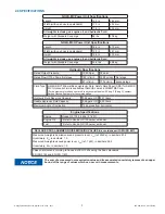
8.0 TROUBLE SHOOTING GUIDE
Any problem not resolved by these suggestions may require you to contact your local dealer or AMKUS, Inc. for further guidance.
PROBLEM
SOLUTION
Engine will not start or poor engine performance
Check Honda owner’s manual.
Rescue tool lacks power or speed
Check hydraulic fl uid level in power unit reservoir.
Fluid leaks at fi ttings or hoses
Check tightness of hose fi ttings.
Replace damaged hoses.
Tools do not operate
Check to see that the power unit is running.
Check to see that the line is charged.
Check hydraulic fl uid level in power unit reservoir.
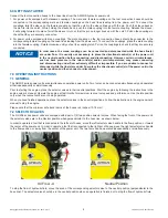
9.0 ROUTINE MAINTENANCE
9.1 ROUTINE MAINTENANCE FOR GASOLINE ENGINE
Follow the maintenance guidelines in the engine owner’s manual.
9.2 ROUTINE MAINTENANCE FOR HYDRAULIC PUMP
Normally, you will have a maintenance agreement for your system with your local dealer. However, if you have decided to service
the equipment yourself, please review the following instructions carefully.
Change hydraulic fluid after each 20 hours of tool operation (approximately every 2 years). If you suspect your hydraulic fluid has
been contaminated in any way, contact your local dealer or AMKUS Rescue Systems.
To change the hydraulic fluid, remove the hydraulic fluid reservoir fill plug/vent cap. Place the unit over a drain pan; unscrew and
remove the drain plug. Be careful not to lose it! Allow the hydraulic fluid to drain completely. Clean and replace the drain plug. Fill
the hydraulic fluid reservoir with new AMKUS mineral base hydraulic fluid. Replace the fill plug/vent cap.
The next step is to purge air from the hydraulic hoses. Please see Set-Up Procedures points 5-9. Check the pressure output of the
power unit at each hose line by connecting a pressure gauge to the pressure line. Move the selector valve to charge the line to
which the gauge is connected.
The rated hydraulic pressure at maximum output is 10,500 psi ± 500 psi (724 bar ±34 bar). Verify performance by periodic testing
using a pressure gage. If performance falls outside of this range, contact your local dealer or AMKUS Rescue Systems.
DO NOT ATTEMPT TO ADJUST THE INTERNAL PRESSURE RELIEF SETTING! Pressure relief valves are NOT user serviceable.
User adjustment is a misuse of this equipment.
Properly dispose of all engine fuel, engine oil, and hydraulic fluid wastes. Do not release chemicals into the environment.
9.3 ROUTINE MAINTENANCE FOR HOSES
After each use, hoses should be wiped clean with a light cleaner such as Simple Green
®
. Inspect hoses for damage to the rub-
ber outer cover. Damage which exposes the wire braided reinforcement subjects the wire to corrosion and may weaken the hose.
Replace damaged hoses.
9.4 ROUTINE MAINTENANCE FOR COUPLINGS
Use care when making hydraulic connections by avoiding dirt, sand, and water puddles at the emergency scene. Even with care,
residual oils on the moving parts will gradually accumulate dirt and grit making connections difficult. Couplings and dust caps can
be periodically cleaned using an automotive type aerosol solvent de-greaser. Avoid water-based cleaning products. Apply a light
spray lube (automotive, lock, or gun type) to keep the collars moving easily. Avoid covering a clean coupling with a dirty dust cap.
Replace damaged fittings.
9.5 MAINTENANCE RECORDS
It is the responsibility of the user to keep maintenance records for each component of the rescue system. Maintenance shall be
performed by qualified service technicians in accordance with the recommendations as outlined in this manual.


