


©Copyright Amkus Rescue Systems, Inc. 2015 - 2017
LAP-006 June 8, 2017 Rev05
6
6.0 GETTING STARTED
Connect the tool connection hoses to the hose lines from the AMKUS hydraulic power unit.
1. For power units equipped with standard couplings: The male and female couplings on the tool connection hoses should be
connected to the corresponding male and female couplings on the hose lines leading from the power unit. To connect the
couplings, twist the sleeve on the female coupling so that the notch in the sleeve lines up with the pin. Push the sleeve back so
the pin fits into the notch. While holding the sleeve back, push the male coupling into the female coupling. Release the sleeve;
it will spring forward into place. Twist the sleeve ¼ turn so that the pin no longer lines up with the notch. Pull on the couplings to
check that they are securely connected.
2. For power units equipped with mono couplings: The male coupling on the tool connection hoses should be connected to the
corresponding female coupling on the hose lines leading from the power unit. To connect the couplings, place the male coupling
into the female coupling. Rotate clockwise until you feel the coupling latch. Pull on the couplings to check that they are securely
connected.
NOTICE
In most cases, the mono couplings can be connected and disconnected while the hose line(s)
are under fl ow. It is usually not necessary to place the directional control(s) of the power unit
in the neutral position before connecting and disconnecting. However, certain circumstances,
such as back pressure in the return line(s) and/or cold temperatures, may make connecting
and disconnecting under fl ow extremely diffi cult or impossible. If you are unable to connect or
disconnect while the line(s) are under fl ow, place the directional control(s) of the power unit in the
neutral position and then connect or disconnect.
7.0 OPERATING INSTRUCTIONS
7.1 GENERAL
The GH2S2 series power units are simultaneous operation power units. Two tools can be connected simultaneously and operated
either independently or simultaneously.
Prior to starting the engine, place the selector valves in their neutral positions. Start the engine by following the instructions in the
engine owner’s manual. Operate the engine at fast throttle for maximum rescue tool speed and performance. Use the idle position
only when the rescue tools are not being operated.
When you have finished operations, place the selector valves in their neutral positions. Follow the instructions in the engine owner’s
manual to stop the engine.
Please note that the minimum safe bend radius of the hoses is 4 inches (101.6 mm).
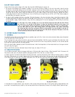
7.2 SELECTOR VALVES
The GH2S2 series power units are equipped with a pair of (2) two position selector valves. When facing the front of the power unit,
the selector valves are in the Neutral position when perpendicular to the hose line, as shown below.
In order to operate a tool that is connected to the left set of hoses, move the left selector valve handle to the flow position, or toward
the center of the power unit. In order to operate a tool that is connected to the right set of hoses, move the right selector valve handle
to the flow position, or away from the center of the power unit. The two tools can be operated independently or simultaneously.
Neutral Position
Oil Flow - A
To stop the flow of hydraulic fluid, move the knob of the corresponding selector valve to the neutral position (perpendicular to the
hose line). The selector valve should be in the neutral position when an operation is finished or to stop the flow of hydraulic fluid.


