background image

4010 ATD LT ASSY/OPER/PARTS MANUAL (74303) 12/08

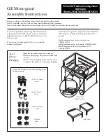
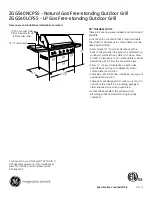
MAIN FRAME PACKER/LIFT ASSEMBLY

 UNLESS SPECIFIED, 

ALL

 HARDW

ARE IS 

SECURED WITH MA

TCHING LOCK NUTS

PART NO.

DESCRIPTION

QTY

PART NO.

DESCRIPTION

QTY

22022

HEADLESS PIN(2) 1-1/4X2-7/16

2

241513

CENTER PACKER HANGER               

2

88666

BLT HEX 1-8NCX6-1/2 5Z

8

241572

ADJUSTMENT SCREW                   

2

89389

BLT HEX 3/4-10NCX2-1/2 8YZ

8

241584

REAR CYLINDER CHANNEL LOCK    

2

234836

REAR BRACE TUBE

2

241623

HYD CYL 4-3/4X8 SEQ                

2

240484

PACKER LIFT ANCHOR                 

2

26120

SEAL                               

4

243073

MAIN FRAME - ATD                   

1

34132

A

XLE CLAMP ASSEMBLY (RED)

8

243995

CENTER PACKER MOUNT                

1

42082

1-1/2NF HYDRA JAM LOCK NUT        

2

12103

BEARING CONE 1-3/4ID (25580)       

4

54599

WALKER BEARING BUSHING            

2

16154

2-1/2IN HUB&SPINDLE ASSY(LG8210011)

4

67854

HEADLESS PIN(2) 1-1/4X3-23/32      

8

16278

BEARING BUSHING                    

2

68399

HEADLESS PIN(2) 1-1/4X7-1/8        

2

221347D1

RIGHT 3X11 HD WALKING TANDEM       

1

88125

NUT HEX 1-8NC  5Z                  

2

221347D1R

LEFT 3X11 HD WALKING TANDEM        

1

88131

WSHR FLAT 3/4(13/16X2ACT)  Z       

8

222213F1

HYD CYL 4X16 FGS #A519CY26         

2

88272

BLT HEX 3/4-10NCX4 5Z              

8

222259

WHL ASSY 31X13.5 8B 10" 12P        

4

88290

BLT HEX 3/4-10NCX2 8YZ             

4

234811

1/2X4 BENT PIN W/HAIRPIN           

2

88291

BLT HEX 3/4-10NCX3 5Z              

4

235245

TANDEM PIN                         

2

88381

BLT HEX 5/8-11NCX4-1/2 5Z          

4

237756D1

REAR LIFT AXLE - LEFT              

1

88398

BLT HEX 1-8NCX4 5Z                 

4

237756D1R

REAR LIFT AXLE - RIGHT             

1

88487

BLT HEX 3/4-10NCX8-1/2 5Z          

8

237961D1

LIFT AXLE PIVOT                    

4

88495

BLT HEX 7/8-9NCX2-1/2 5Z           

8

240488

PACKER LIFT BRACKET                

2

88602

WSHR FLAT 1-1/4(1-3/8X3ACT) Z      

20

240554

REAR LIFT MAST                     

2

88767

PIN ROLL 1/4DIAX2-1/2 Z            

24

240567

MAIN MAST TUBE                     

2

89371

BLT HEX 1-8NCX3-1/2 8YZ            

4

240572

LIFT MAST TUBE                     

2

89389

BLT HEX 3/4-10NCX2-1/2 8YZ

8

25

Summary of Contents for FARGO AIRE 4010

Page 1: ...Printed in USA 74303 11 7 08 ASSEMBLY OPERATORS PARTS MANUAL FARGO AIRE Amity Technology LLC 2800 7th Avenue North Fargo ND 58102 701 232 4199 www amitytech com TILL DRILL 4010 ...

Page 2: ...s of notice by Amity 3 Procedures for Obtaining Service To secure Warranty service a purchaser must 1 report the defect to an authorized dealer and request repair within 45 days of the failure and within the Warranty Period 2 present evidence that this Warranty applies to the Product 3 present evidence of the Warranty Start Date and 4 bring the Product to an authorized Amity dealer within a reason...

Page 3: ...bol be alert to the possibility of personal injury or death Follow the instructions in the safety message Why is SAFETY important to you 3 Big Reasons Accidents Disable and Kill Accidents Cost Accidents Can Be Avoided SIGNAL WORDS Notetheuseofthesignalwords DANGER WARNING and CAU TION with the safety messages The appropriate signal word for each message has been selected using the following guidel...

Page 4: ...as you proceed and make sure they work freely Looselyinstallallboltsconnectingmatingparts before final tightening When tightening bolts they must be torqued to the proper number of foot pounds as indi cated in the table unless specified It is impor tant that all bolts be kept tight On new machines all nuts and bolts must be rechecked after a few hours of operation ASSEMBLY INFORMATION Common Abbre...

Page 5: ...er machine and for having parts repaired or replaced when continued use of this product would cause damage or excessive wear to the otherparts ThewordNOTEisusedtoconveyin formationthatisoutofcontextwiththemanual text special information such as specifications techniques reference information of supple mentary nature Wheninneedofparts alwaysspecifythemodel and serial number Write this number in the...

Page 6: ...gs Attach the packer lift anchors 20 21 center in the adjustment slot and adjustment bolt to all rear packer sections Secure the front lift masts to the front main frame tube 16 18 UNIT ASSEMBLY PROCEDURE Read and review all assembly instructions before starting assembly of this unit This unit will be packed in a condensed format usually on a packaging skid This package may be very heavy and will ...

Page 7: ...and attach the left and right rear lift axles to the lift axle pivots 24 as shown and secure Insert hubs spindles and rims and tires TRANSPORT LIFT CIRCUIT There is a single set of lift cylinders that are used to lift and hold the rear of the unit in the transport position These cylinders are connected in a simple circuit as noted 40 Attach the base end of the 4x16 cylinders to the rear lift mast ...

Page 8: ...ders All cylinders should retract in sequence Fully extend the cylinders again and check to ensure all cylinders are purged and fully extended and are moving in sequence NOTE It may require that the main lift system be re sequenced periodically during use CHARGING WING FOLD CIRCUIT Connect the wing fold circuit to the oil supply and apply pressure The main frame wing fold cylinders will slowly ext...

Page 9: ...less challenging Once the main lift system has been purged and sequenced lower the unit down so the shanks are 1 to 2 above the ground as shown below Measure the distance to the ground from a point of a shank on the front rank of the unit Pick a shank on the outside of the main frame Measure from the same point of a shank on outside rear of the unit If the main frame is not level front to rear an ...

Page 10: ...adjustments to the various anchors have been completed there should be minimal need to readjust these settings When the unit has been moved to the field and dropped to the seeding depth it is important to recheck the front to rear level and depth of each section Variations in soil type and loading will effect the operational depth and readjustments may be required The adjustments noted above are t...

Page 11: ...en folding the unit in loose ground conditions Skidding can be reduced by slowly moving forward with the unit as the wings are folded Forward movement is only required when the wing packer wheels are skidding WING FOLDING UNFOLDING Continue to fold the inner wings these wings should fold to a slight over center position Once the wing have come to rest in the wing rest clevis active the main lift c...

Page 12: ...pport under the lift wheels to prevent sinking into the ground When storing the unit at any time if hitched to a tractor or not always relieve the pressure to the wing fold circuit This can be accomplished by using the float circuit of the tractor Move the hydraulic lever to the float position to relieve pressure in the wing fold circuit before turning off or unhitching the tractor FIELD OPERATION...

Page 13: ...the packer spring to increase the holding force As with all machinery it will be necessary to check the tightness of all hardware after 4 6 hours of use As the various components seat there will be parts that need to be adjusted Hardware that is retaining parts that do not rotate or move should be checked after the first day of use and weekly after that Parts such as packer wheel pivots or parts t...

Page 14: ...ding the general layout of the unit Please refer to the individual assembly instructions for specific information HDW KIT 74303 X Information in these boxes reference the corresponding Hardware Kit that contains the hardware used to assembly the portion of the unit noted on that page UNLESS SPECIFIED ALL BOLTS ARE SECURED WITH TOP LOCK LOCK NUTS 14 ...

Page 15: ...urealltools parts orservice equipment is removed from the machine Make sure there is no one near the machine before or during operation DURING OPERATION Reducespeedwhencorneringonfieldendsand when operating on or across dead furrows Do not attempt to remove any obstruction while the machine is in motion Use extreme care when operating close to ditches fences or on hillsides No one other than the o...

Page 16: ...MAIN HITCH BY INSERTING 89279 THRU HOSE HOLDER SHIM BETWEEN LEGS WITH BUSHING BACKING PLATE FLAT WASHERS PROVIDED IN MAIN HDW HOSE HOLDER KIT MAIN FRAME FRONT HITCH ASSEMBLY HDW KIT 74303 1 REMOVE SAFETY CHAIN HOOK INSERT INTO CHAIN LOOP ON BOTTOM OF HITCH AND RE ATTACH THE CHAIN HOOK 16 ...

Page 17: ...TED 2 88293 BLT HEX 3 4 10NCX6 5Z 18 241677 SENSOR MOUNT 1 88295 BLT HEX 5 8 11NCX6 5Z 4 241678 SENSOR PLATE 1 88305 BLT HEX 3 4 10NCX5 5Z 2 241679 TIE STRAP 1 88352 PIN SPRLK 3 16X3 1 4 PRLS6 Z 4 241777 BACKING PLATE BLACK 1 88362 WSHR HLK 3 8ID Z 2 242932 LARGE WEAR PLATE 2 88381 BLT HEX 5 8 11NCX4 1 2 5Z 4 243034 MAIN HITCH 40FT ATD LT 1 88404 BLT HEX 3 4 10NCX2 1 2 5Z 4 243044 RIGHT MAIN AXLE ...

Page 18: ...4010 ATD LT ASSY OPER PARTS MANUAL 74303 12 08 MAIN FRAME LIFT WHEEL ASSEMBLY HDW KIT 74303 4 18 ...

Page 19: ...8YZ 2 235245 TANDEM PIN 1 88293 BLT HEX 3 4 10NCX6 5Z 11 235801 PIVOT PIN 1 1 2 X 10 2 88305 BLT HEX 3 4 10NCX5 5Z 1 237792 OUTER LINK ARM 1 88381 BLT HEX 5 8 11NCX4 1 2 5Z 2 241563 TOP TUBE 1 88404 BLT HEX 3 4 10NCX2 1 2 5Z 4 241624 HYD CYL 5X8 SEQ 1 88430 NUT 2POSLK 1 1 4 7NC 5Z 1 242932 LARGE WEAR PLATE 1 88581 BLT HEX 3 8 16NCX2 1 4 5Z 2 243073 MAIN FRAME ATD 10 INCH LT 1 88582 BLT HEX 3 8 16N...

Page 20: ...ER MOUNT 1 88428 BLT HEX 1 1 4 7NCX9 5Z 2 240577 WING MAST TUBE 1 88430 NUT 2POSLK 1 1 4 7NC 5Z 4 241513 CENTER PACKER HANGER 2 88487 BLT HEX 3 4 10NCX8 1 2 5Z 4 241572 ADJUSTMENT SCREW 1 88602 WSHR FLAT 1 1 4 1 3 8X3ACT Z 4 241622 HYD CYL 4 1 2X8 SEQ 1 88610 WSHR FLAT 1 1 2SAE 1 9 16X3 Z 2 241699 WING FOLD ROLLER 1 88658 NUT TOP LK 1 8NC 5Z 5 243049 LEFT WING 40FT ATD LT 1 88665 NUT TOP LK 3 4 10...

Page 21: ... 1 1 4 7NCX9 5Z 2 241572 ADJUSTMENT SCREW 1 88430 NUT 2POSLK 1 1 4 7NC 5Z 4 241622 HYD CYL 4 1 2X8 SEQ 1 88487 BLT HEX 3 4 10NCX8 1 2 5Z 4 241699 WING FOLD ROLLER 1 88602 WSHR FLAT 1 1 4 1 3 8X3ACT Z 4 243048 RIGHT INNER ATD WING LT 1 88610 WSHR FLAT 1 1 2SAE 1 9 16X3 Z 2 243073 MAIN FRAME ATD 10 INCH LT 1 88658 NUT TOP LK 1 8NC 5Z 5 243904 MAIN FRAME FOLD BRACKET 1 88665 NUT TOP LK 3 4 10NC 5Z 16...

Page 22: ...9 WALKER BEARING BUSHING 1 222338 HEADLESS PIN 2 1X4 1 8 1 88103 NUT HEX 3 8 16NC 5Z 8 235245 TANDEM PIN 1 88272 BLT HEX 3 4 10NCX4 5Z 1 235801 PIVOT PIN 1 1 2 X 10 1 88293 BLT HEX 3 4 10NCX6 5Z 9 237712 FRONT MAST MOUNT ATD 1 88295 BLT HEX 5 8 11NCX6 5Z 2 237714D1 LEFT OUTER WALKER ATD 1 88362 WSHR HLK 3 8ID Z 8 237714L1 RIGHT OUTER WALKER ATD 1 88507 BLT HEX 1 2 13NCX3 1 2 5Z 2 237722D2 WING FRO...

Page 23: ...4010 ATD LT ASSY OPER PARTS MANUAL 74303 12 08 THIS PAGE INTENTIONALLY LEFT BLANK 23 ...

Page 24: ...4010 ATD LT ASSY OPER PARTS MANUAL 74303 12 08 MAIN FRAME PACKER LIFT ASSEMBLY HDW KIT 74303 5 NOTE Springs are installed down where depth cylinder anchors are located 2 plac es where arrows point to 24 ...

Page 25: ...7854 HEADLESS PIN 2 1 1 4X3 23 32 8 16278 BEARING BUSHING 2 68399 HEADLESS PIN 2 1 1 4X7 1 8 2 221347D1 RIGHT 3X11 HD WALKING TANDEM 1 88125 NUT HEX 1 8NC 5Z 2 221347D1R LEFT 3X11 HD WALKING TANDEM 1 88131 WSHR FLAT 3 4 13 16X2ACT Z 8 222213F1 HYD CYL 4X16 FGS A519CY26 2 88272 BLT HEX 3 4 10NCX4 5Z 8 222259 WHL ASSY 31X13 5 8B 10 12P 4 88290 BLT HEX 3 4 10NCX2 8YZ 4 234811 1 2X4 BENT PIN W HAIRPIN...

Page 26: ...M 1 8NC 5Z 4 237986 SPRING PLATE PAINTED BLACK 1 88162 NUT 2POSLK 3 8 16NC 5P 2 237996 WALKER PIVOT WASHER 4 88489 BLT HEX 3 8 16NCX2 1 2 8YZ 2 239169 SPRING PAINTED BLACK 1 88661 NUT TOP LK 1 2 13NC 5Z 2 240479 CENTER PACKER MOUNT 1 88665 NUT TOP LK 3 4 10NC 5Z 1 240480 PACKER WALKER 10 IN 1 88680 BLT HEX 1 2 13NCX3 1 4 5Z 1 241541 INNER PACKER PLATE BLACK 1 89462 BLT HEX 3 4X10NCX10 1 2 8Z 1 241...

Page 27: ...R WINGS TO A 1 4 TO 3 8 DIMENSION 4 CHECK TO ENSURE THAT THE SPRING PLATE TO FRAME STOP CONTACT IS MAINTAINED TO ENSURE THAT ALL PACKERS ARE SET TO THE SAME DEPTH 5 PROCEED TO COMPLETING THE FIELD SETTINGS AND CHECK TO SEE THAT THE STOP CONTACT IS MAINTAINED AS THE UNIT MOVES THROUGH THE FIELD IF THE PACKER PIVOTARMS ARE MOVING EXCESSIVELY DUE TO NORMAL LOADING NOT OBSTRUCTIONS TIGHTEN THE SPRING ...

Page 28: ...TE RED 1 88531 BLT HEX 3 8 16NCX3 5Z 7 243073 MAIN FRAME ATD 10 INCH LT 1 88541 BLT HEX 1 2 13NCX3 5Z 2 243908 ATD HITCH SHORT FRONT 1 88659 NUT TOP LK 3 8 16NC 5Z 21 243913 MAIN FOLD ANCHOR 1 88661 NUT TOP LK 1 2 13NC 5Z 2 243928 REAR PULL HITCH 1 88665 NUT TOP LK 3 4 10NC 5Z 24 243936 HITCH SIDE BRACE 2 88845 NUT TOP LK 5 8 11NC 5Z 12 243987 PACKER OPEN END WRENCH 1 89389 BLT HEX 3 4 10NCX2 1 2 ...

Page 29: ...3 4 10NC 8YZ 1 57945 16 12 SPRING ASSEMBLY 2 89385 BLT HEX 3 4 16NFX6 1 2 8YZ 2 57963 CAST SPRING PLUG 1 89386 NUT NYL 3 4 16NF 8YZ 2 58032 HDN 1 2 X 2 1 2 BOLT Z 2 89398 BLT HEX 5 8 11NCX6 1 2 8YZ 24 62589 DUCTILE PIVOT ARM 1 241674 3 8 IN SHANK SHIM 12 62639 STOP COLLAR 1 243954 EDGE ON CP SHANK ASSY BLACK 1 88126 NUT HEX 5 8 11NC 5Z 2 243955 CP SHANK ASSY 32IN BLACK 1 88129 WSHR HLK 5 8ID 11 16...

Page 30: ... HEX 50 NC ZP 8 3 234513 GUARD STRAP 1 17 1023854 BOLT CRG 50 X 1 25 NC GR5 ZP 2 4 66477 ASSY CENTER CARRIER 1 18 1011606 BOLT HEX 50 X 1 25 NC GR5 ZP 2 5 67133 PLATE BACKING 2 19 33036 WASHER FLAT 50 ZP HD AR 6 1016362 BOLT CRG 38 X 1 25 NC GR5 ZP 4 20 1011624 BOLT HEX 63 X 3 00 2 7 1016999 NUT TOPLOCK 38 NC GR5 ZP 4 21 1026259 NUT JAM 63 NC GR2 ZP 4 8 234504 BOLT HEX 75 X 5 75 1 22 66057 DUST CA...

Page 31: ...PTION QTY 10344 BEARING CUP 2 328 OD 1 10345 BEARING CONE 1 1 4 ID 1 23029 BEARING CONE 3 4 ID 1 23097 SEAL 1 23101 BEARING CUP 25 32 OD 1 23103 DUST CAP 1 237800 PACKER WHEEL 1 55927 4 BOLT WHEEL HUB 1 58054 4BOLT PRESSED HUB 1 88142 BLT WHL 1 2 20NFX1 4 88300 NUT SLTD 3 4 16NF 5Z 1 88548 WSHR FLAT 3 4SAE Z 1 88560 PIN COT 1 8DIAX1 1 4 Z 1 31 ...

Page 32: ...BEARING CUP 2 328 OD LM67010 2 10345 BEARING CONE 1 1 4ID LM67048 2 244585 PACKER SPINDLE 1 88300 NUT SLTD 3 4 16NF 5Z 1 89461 BLT WHL 1 2 20 UNF X 75 4 88548 WSHR FLAT 3 4SAE 13 16X1 1 2 Z 1 88550 FTG GRS 1 4 28 3038 B 1 88560 PIN COT 1 8DIAX1 1 4 Z 1 A33555 SEAL RETAINER 1 A33556 SEAL COUNTERFACE 1 A33557 V SEAL 1 A33879 HUB CAP 1 A34545 PACKER HUB 1 32 ...

Page 33: ...4ID LM67048 4 24097 6 BOLT HUB W CUPS 5 10344 BEARING CUP 2 328 OD LM67010 6 88263 FTG GRS 1 8NPT 1610 BL 11 16 7 14249 BEARING CUP 2 891 OD LM501310 8 58546 2 TRIPLE LIP SEAL 9 88429 1 2NFx3 1 4 GR5 BOLT 10 88304 NUT 2POSLK 1 2NF 11 14251 2 AXLE SPINDLE 12 14248 BEARING CONE 1 5 8ID LM501349 13 88142 WHEEL BOLT 1 2NFx1 13 16 HEAD 14 88340 NUT SLTD 7 8NF 15 11381 DUST CAP 77836 PLT 1 2 3 4 6 8 11 ...

Page 34: ...ASE FITTING 7 16080 2 1 2 SINGLE LIP SEAL PRIOR 2003 235298 2 1 2 SINGLE LIP SEAL 2003 AND UP ITEM PART NO DESCRIPTION 8 16156 2 1 2 AXLE SPINDLE 14 3 4 9 88298 5 8NCx4 GR5 BOLT 10 88369 5 8NC LOCK NUT 11 16083 INNER BEARING CONE TIMKEN 3780 12 16084 INNER BEARING CUP TIMKEN 3720 13 63831 9 16NFx1 1 8 90 WHEEL BOLT 14 88299 1NF SLOTTED NUT 15 16077 DUST CAP 16 222259 31x13 5 12 PLY 8 BOLT WHEEL AS...

Page 35: ...DS IF REQUIRED FAILURE TO ORIENTATE AS INDICATED CAN CAUSE PORT INTERFERENCE CHECK FOR INTERFERENCE BEFORE AND WHILE ACTIVATING ALL CYLINDERS MAIN LIFT BYPASS CYLINDER CIRCUIT REFER TO PAGE 38 FOR CYLINDER LOCATIONS ON THE MAIN UNIT NOTE ORIENTATION OF FRONT CYLINDERS ON THE LEFT SIDE OF THE UNIT HYD CYL 5X8 HYD CYL 4X8 HYD CYL 4 3 4X8 HOSES TO TRACTOR HYD CYL 4 1 2X8 HYD CYL 4 1 2X8 HYD CYL 5X8 H...

Page 36: ...R STOP BLUE 233838 SEAL KIT 4IN FGS SK ACGZ4Q2Q 241670 SEAL KIT 4IN ATD BP CYL 241645 1 2IN CYLINDER STOP RED 241671 SEAL KIT 4 1 2IN ATD BP CYL 241646 5 8IN CYLINDER STOP ORANGE 241672 SEAL KIT 4 3 4IN ATD BP CYL 241647 3 4IN CYLINDER STOP YELLOW 241673 SEAL KIT 5IN ATD BP CYL 241649 1 1 2IN CYLINDER STOP GRAY W104625 SEAL KIT 5X36 CYL 244587 1 1 4IN CYLINDER STOP GREEN 36 ...

Page 37: ... B 2 18 Y B 4 R R GY GY 5 75 Y Y GN GY 2 25 Y GY 4 06 R O B GY 5 81 R R O GN GY 2 38 R O GN 4 12 R O GY GY 5 88 R R O GN GY 2 44 R R B 4 18 GN B GY 5 94 R R Y GN GY 2 5 R R GY 4 25 GN GY GY 6 R R Y GN GY 2 56 R O B 4 31 O Y B GY 606 R R O Y B GY 2 62 R O GY 4 38 O Y GY GY 6 12 R R O Y GY GY 2 69 R Y B 4 44 Y Y B GY 6 18 R Y Y GN GY 2 75 R Y GR 4 5 Y Y GY GY 6 25 R Y Y GN GY 2 81 O Y B 4 56 R R O B...

Page 38: ...4010 ATD LT ASSY OPER PARTS MANUAL 74303 12 08 HOSE ROUTING MAIN LIFT 2 1 LIFT HOSE DECALS 13 12 SECURE HOSES FRAME TUBES WITH NYLON TIES HDW KIT 74303 7 38 ...

Page 39: ...E HOSES TO REAR HITCH CLAMPS AND FRAME TUBES WITH NYLON TIES HDW KIT 74303 8 12 11 ITEM PART NO DESCRIPTION QTY 1 13234 ADP 8MJ X 8MPT 2 2 13238 TEE 8MJ X 8MJ X 8MJ 2 3 13239 UNION 8MJ X 8MJ 2 4 13268 HSE 3KPSI 3 8X78 8FJX 8FJX 2 5 14644 HSE 3KPSI 3 8X36 8FJX 8FJX 2 6 25580 ELB 8MORB X 8MJ 2 7 237264 HSE 3KPSI 1 2X234 8FJX 8FJX 2 8 222199 HSE 3KPSI 1 2X24 8FJX 8FJX 2 9 60640 QUICK DISCONNECT COUPL...

Page 40: ...tting require some type 7 SECURE HOSES TO REAR HITCH CLAMPS AND FRAME TUBES WITH NYLON TIES HDW KIT 74303 9 ITEM PART NO DESCRIPTION QTY 1 13234 ADP 8MJ X 8MPT 2 2 13238 TEE 8MJ X 8MJ X 8MJ 2 3 13482 HSE 3KPSI 3 8X10⁸ 8FJX 8FJX 2 4 13483 HSE 3KPSI 3 8X120 8FJX 8FJX 2 5 222199 HSE 3KPSI 1 2X24 8FJX 8MJ 2 6 237264 HSE 3KPSI 1 2X234 8FJX 8FJX 2 7 25580 ELB 8MORB X 8MJ 4 8 60640 QUICK DISCONNECT COUPL...

Page 41: ...HOSE 241747 2EA 3 4X456 8MPT 12MPT CASE DRAIN HOSE 241748 1EA 1 2X456 8MPT 8MPT 1 2 FEMALE PIONEER COUPLER 236170 1EA 60640 QUICK DISCONECT COUPLER 3EA 3 4 FEMALE COUPLER 240301 2EA 1 2 FEMALE COUPLER 239899 1EA 3 4 FEMALE COUPLER 240301 1 2 FEMALE COUPLER 239899 QUICK DISCONNECT MALE COUPLER 60640 1 2 FEMALE PIONEER COUPLER 236170 SECURE HOSES TO HOSE BRACKETS SPACED ALONG REAR HITCH TUBE WITH CL...

Page 42: ...10 ATD LT ASSY OPER PARTS MANUAL 74303 12 08 RIGHT SIDE SHANK SPACINGS MOUNT TO FRONT MAST SUPPORT PLATE USE 221196 SUPPORT PLATE MOUNT UNDER REAR HITCH W PLATE MOUNT TO WING FOLD CYLINDER MOUNT PLATE 42 ...

Page 43: ...4010 ATD LT ASSY OPER PARTS MANUAL 74303 12 08 LEFT SIDE SHANK SPACINGS MOUNT TO WING MOUNT PLATE USE 221196 MOUNT PLATE 43 ...

Page 44: ...HRS DECAL LOCATIONS GREASE FITTINGS Check walker spindle nut and adjust to a heavy drag after the first 40 hrs of use and monthy thereafter Check wheel hub and spindle nut and adjust to a moderate drag after the first 40 hrs of use Recheck monthy thereafter Repack bearings at end of season MAIN AND WING LIFT WHEELS 44 ...

Page 45: ... SINGLE AMBER TRI PLUG 2 223144 AG LIGHT SINGLE RED TRI PLUG 2 223160 12 LIGHT ARM 2 240238 48IN OFFSET LIGHT ARM W LOCK 2 88103 NUT HEX 3 8 16NC 5Z 12 88172 NUT HEX 1 4 20NC 5Z 16 88203 BLT HEX 1 4 20NCX1 5Z 16 88262 WSHR HLK 1 4ID 5 16ACT Z 16 88362 WSHR HLK 3 8ID Z 2 88702 SCR SET 3 8NCX3 4 SQHD CUP PT P 10 89034 BLT HEX 3 8NC X 1 5Z 2 45 ...

Page 46: ...Keep safety decals clean Replace any safety decals that are damaged destroyed missing paintedoverorcannolongerberead Replace ment safety decals are available through your dealer 3 16NCx5 8 BOLT SAFETY SMV EMBLEM SAFETY LIGHTS NOTE REFER TO LIGHT PLACEMENT INSTRUC TIONS SPECIFIC TO THIS UNIT THIS SHOWS BASIC WIRE CONNECTIONS NOTE MOUNTAMBERLIGHTSASWIDEASPOS SIBLE THE AMBER LIGHTS MUST BE MOUNTED NO...

Page 47: ... 1 8 1026358 CLAMP HOSE 16 0 81 1 50 3 9 33920 WLDMT PRIMARY TUBE 4 W FL PC 1 10 33503 NUT WING SS M6 X 1 0 6 11 33502 BOLT HEX SS M6 X 1 0 X 50 FULL 6 12 33947 RUBBER PAD SNAP IN 4 50 2 13 33856 U BOLT 500 X 5 50 X 8 X 5 50 4 14 1011581 WASHER LOCK 50 ZP 8 15 1011577 NUT HEX 50 NC GR2 ZP 8 16 66157 ASSY 4 VERTICAL TUBE CLAMP 2 17 1013239 BOLT HEX 38 X 3 00 NC GR5 ZP 2 18 1016999 NUT HEX 38 NC GR5...

Page 48: ...ASSY OPER PARTS MANUAL 74303 12 08 Mount primary tubes 30 on center from the inside of frame tube shown Left side shown right side opposite Mount primary tube on third cross tube from the front of the machine 30 48 ...

Page 49: ... 8 53159 SPRING EXTENSION 4 9 33334 PLATE GENERIC SPRING MNT 3 10 34289 CINCH STRAP VELCRO 1 50 X 24 20 11 33342 PLATE SPRING MOUNT BACKING 1 12 33856 U BOLT 500 X 5 50 X 4 X 5 50 3 13 1011669 BOLT HEX 50 X 6 0 NC GR5 ZP 2 14 1011581 WASHER LOCK 50 ZP 6 15 1011577 NUT HEX 50 NC GR2 ZP 6 16 66157 ASSY 4 VERTICAL TUBE CLAMP 2 17 66145 ASSY FLOW DIVIDER 1 18 65745 ASSY ROLLING MOUNT FLOW DIVIDER 1 19...

Page 50: ...RTICAL 8 5 66144 ROLLER ROLLING MNT VERTICAL SHORT 4 6 66165 ROD THREADED 500 X 12 00 ZP 4 7 1011618 BOLT HEX 50 X 5 00 NC GR5 ZP 4 8 1032506 NUT FLANGE 50 NC GR5 ZP 32 9 1027461 NUT TOPLOCK 50 NC GR5 ZP 4 10 1033298 U BOLT MUFFLER CLAMP 5 00 2 11 65720 NUT FLANGE 38 NC GR2 ZP 4 12 66146 WLDMT FLOW DIVIDER PC 1 13 66114 WLDMT MANIFOLD POINTER ZP 1 14 1025601 PIN ROLL 19 X 1 00 ZP 1 15 66166 WLDMNT...

Reviews: