


6
Amico Corporation
Description of Modules
COMMON TO ALL ALARMS
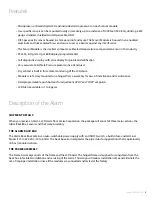
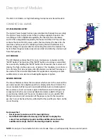
SYSTEM POWER SUPPLY
The System Power Supply has been pre-installed into the back box assembly.
The System Power Supply converts the AC voltage supply to the alarm into
two voltages: 5 VDC (regulated) required by the microprocessor hardware
and 15 VDC (unregulated) required by the buzzer and the LCD. This unit also
contains the main ON/OFF power switch, the transformer, the heat sink, the
main fuse and fuse cover, the rectifying circuitry, the terminal blocks and
the low voltage DC power cable for connecting this unit to the module. The
System Power Supply can be easily removed and reinstalled by unscrewing it
from the back box.
LCD MODULE
The LCD Module contains the LCD screen, microprocessor, buzzer and the
“MUTE” button. The function of the “MUTE” button is to silence an alarm that
has occurred. By holding the “MUTE” button for 20 seconds, the module will
display the high and low pressure set points. This module also contains a
fail-safe relay that de-energizes when the buzzer is activated. This relay can
be used with the Amico Remote Buzzer for applications requiring a remote
audible alarm, master alarm or a Building Management System.
SENSOR MODULE
The Sensor Module contains the transducer which converts the source of the
pressure/vacuum into a digital signal that is displayed on the LCD alarm. The
sensor module shall be housed in an anodized aluminum and nickel-plated
brass enclosure to act as a barrier against interference and it is temperature
compensated. Each sensor is clearly labeled and color coded for the gas or
vacuum being monitored. The sensor module contains a gas-specific DISS
fitting to ensure correct connection of the proper sensor to the respective
gas. Each sensor has been factory calibrated for the specific gas shown on the
sensor housing.
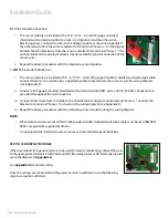
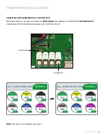
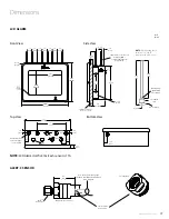
AC Supply
115 to 220 VAC
DC Power Cable:
Connect to
Annunciator Module
G
N
L
L - Live
N - Neutral
G - Ground
Fuse (1 AMPw)
Ground
Toggle Switch
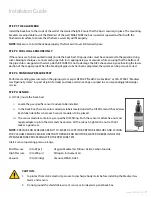
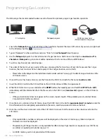
The Alert-3 LCD Alarm is a high technology microprocessor based module:
For Annual Test
• Reset power to make sure LCD screen lights up
• Hold the MUTE button for twenty (20) seconds to display the
current low and high set points and the audible alarm. Once the
audible alarm stops, the LCD Alarm will go back to normal.
NOTE:
Do not press “mute button” while on test mode. If press, it will repeatedly show current set points.


