


www.amico.com
27
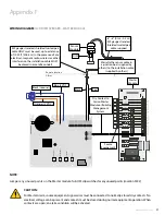
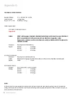
Appendix F
WIRING DIAGRAM:
LCD DISPLAY BOARD - MASTER MODULE
#22 Gauge twisted
pair shielded cable
5,000' [1,500m] max.
Sensor
Module
DISS
Junction Box
(by others)
Remote location
Alarm
Master
Module
Note: Jumper any unused points
on the Master module.
U
2
U
6
U
5
U4
U4
U3
NC
C
NC
C
NC
C
NC
C
NC
C
NC
C
NC
C
NC
C
Source
Equipment
C
H
1
C
H
2
C
H
3
C
H
4
C
H
5
C
H
6
C
H
7
C
H
8
C
H
9
C
H
1
0
ON
1
2
3
4
#22 Gauge twisted
pair shielded cable
6"-8” [0.1 m-0.2 m]
supplied
OXY
GEN
ON
1
2
3
4
5
6
7
8
9
10
+
+
+
+
+
+
+
+
+
+
AC Supply
115 to 220 V
AC
DC P
ower Cable
:
Connect to
Annunciator Module
G
N
L
L - Live
N - Neutral
G - Ground
Fuse (1 AMPw)
Ground
Toggle S
wit
ch
B4
B3
B2
B1
SE
TUP
CHANGE UP
CHANGE DOWN
SELEC
T/MUTE
NOTE:
Jumper any unused points on the Master module. Turn OFF dip-switches for any unused points (Location SW-2)
S1
S2
-
+
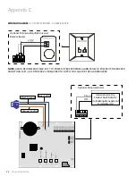
CAUTION:
For Master Alarm, source equipment signal wires must be connected to normally-closed dry contacts. No
electrical voltage can be present and contacts must be closed during normal equipment operation. When
contacts are open; an alarm condition will be activated.
Sensor
Module
Master
Module
Source
Equipement
DISS
#22 gauge stranded, shielded twisted pair
cable ONLY must be used, up to a distance
of 1000 ft [304.8 m]. In the presence of any
electrical, magnetic radio, wireless or other
interference, the installation cable MUST
be placed in a metallic conduit
6" - 8" [0.1m - 0.2 m]
#22 gauge stranded,
shielded twisted pair
cable supplied
Dry Contact to
Amico Master
Module or Building
Management
System
Marrette the sensor cable in
a junction box (supplied by
others) to the installation cable
(supplied by others)
Black
Red
Orange (15 VDC)
Blue (5 VDC)
Black (Ground)


