


Table of Contents
Pressure Only
13
HIGH/LOW Alarm Set Point Adjustments
13
PSI/kPa/BAR selection
14
Vacuum Only
14
LOW Vacuum Alarm Set Point Adjustment
14
InchHg/kPa/BAR selections
15
Common Settings for Pressure and Vacuum
15
Repeat Alarm Enable/Disable
15
Setting Factory Default
15
Setting Gas Identification Switches
16
Chart of Gas Specific Settings of Dip-Switches
16
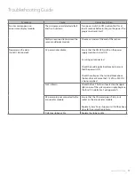
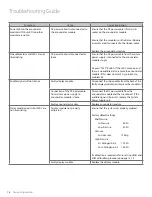
Troubleshooting Guide
17-19
Table of Error Codes
17-19
Error Code Messages on the Display Module
19
Model Numbers
20-21
Spare Parts Numbers
22
Dimensions
23
Appendix A
- Wiring Diagram - Auto-Switching Power Supply
24
Appendix B
- Wiring Diagram - Annunciator
25
Appendix C
- Wiring Diagram - Alarm Valve Combo Unit
26
Appendix D
- Wiring Diagram - Remote Alarm Valve Combo Unit
27
Appendix E
- Wiring Diagram - Alarm Valve Combo Unit to Master Module
28
Appendix F
- Technical Specifications
29
Wiring
30
General Requirments
30
Low Voltage Wire Type
30
www.amico.com
3


