Doc No. 740124
13
MODEL
9 SERIES WELD HEAD
OPERATION MANUAL
7.0 ELECTRODE GEOMETRY & INSTALLATION
(cont’d.)
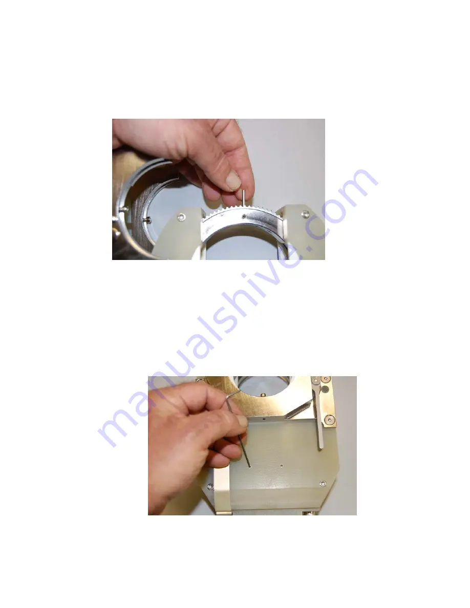
Fig. 14
Install the electrode so the back end is flush with the rotor
outside diameter.
Caution
Do not leave any part of the electrode
protruding past the rotor O.D.
7.6 Two spare electrode set screws may be found in the weld head cover.
See Fig. 15.
Fig. 15
Model 9-2500


