AMG Systems Ltd. reserves the right to make changes to this document without
notice. The information herein is believed to be accurate. No responsibility is
assumed by AMG for its use.
Page 7 of 8
AMG2783R-1-DR-SF
Instruction Sheet D15680-
00
Video input channel configuration
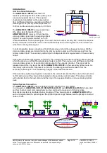
The video present on the video input can be inserted on one of eight video channels transmitted on
the optical fibre. The input channel number is set by SW1 on the primary channel TX board. (See
below for
removal of the PCB
and access to SW1)
The channel number is set by the SW1 switch positions 1 to 3 – see below.
Video Input Channel Number
SW1
position 1
SW1
position 2
SW1
position 3
1
OFF
OFF
OFF
2
ON
OFF
OFF
3
OFF
ON
OFF
4
ON
ON
OFF
5
OFF
OFF
ON
6
ON
OFF
ON
7
OFF
ON
ON
8
ON
ON
ON
It is normal to set each AMG2700 insert unit to a different channel number. If a number is used twice
the second unit connected ‘down stream’ on the primary optical route will ‘over-write’ the first unit and
the video signal will be lost.
The channel number is only required to be set on SW1 on the primary channel TX card. Positions 1 to
3 on SW1 on the secondary channel TX card do not effect the operation of the equipment.
SW1 Switch Settings
Only switch positions 1 to 3 should be set by the user, all other switch settings are set at the factory as
follows:
Primary Channel TX Card (Single Channel Video TX Card)
Switch
Position
Description
Setting
1
Video channel configuration
See above
2
Video channel configuration
See above
3
Video channel configuration
See above
4
Primary / Secondary Board Setting
ON
5
Dual Redundant / Not dual redundant
ON
6
Not Used
OFF
7
Not Used
OFF
8
On board data / Separate data card
ON
9
RS232 Select
OFF
10
RS232 Select
OFF


