


AMG Systems Ltd. reserves the right to make changes to this document without
notice. The information herein is believed to be accurate. No responsibility is
assumed by AMG for its use.
Page 6 of 8
AMG2783R-1-DR-SF
Instruction Sheet D15680-
00
Physical Information
Dimensions
Height .................................................. 3U Plug-in
Width.................................................... 14HP
Depth ................................................... 170mm excluding connectors
Weight.................................................. 800grams
Mounting Details
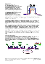
The unit is designed to be mounted within a 2005 Subrack on standard card guides. Note the AMG
standard racks are supplied with guide rails every 14HP. In order to fit this unit in the Subrack with 21
HP plug-ins, some sets of card guides may have to be moved by pulling gently on the card guides.
The 2005 series subrack is fitted with a 1 00 watt power supply.
Configuration of the Data Channel
SW1 and SW2 determine the protocol of the data channel. This can be RS232, RS485 or RS422.
(See below for
removal from the case
and access to SW1 and SW2)
Mode 1 –
RS485 two wire half duplex transmission.
Mode 2 –
RS422 four wire full duplex transmission.
In this mode the RS422 output will transmit a tristate condition as well as logic high and
logic low for systems which require bus-ing of the RS422 four-wire connection.
MODE
Configuration Details
SW2
position
1
SW2
position
2
SW2
position
3
SW2
position
4
SW1
position
9
SW1
position
10
1
RS-422 4 wire Point-to-Point -
and RS-422 BUS system
OFF
OFF
OFF
OFF
OFF
OFF
2
RS-485 2 wire BUS systems
OFF
ON
ON
ON
OFF
OFF
Note: - when used with a 2788 with the individual channel A data channels routed to a separate
data card (not on -board data at the RX), RS485 operation and the tri-state RS422 output is not
available. RS485 operation can only be selected if on -board data is selected at the RX.
The data input for both the RS485 and the RS422 modes detects a tri-state input condition by
monitoring the differential voltage level across the input. A differential level below 500mV positive or
negative will be detected as a tristate condition. A level above 500mV positive or negative will be
detected as a logic 1 or logic zero respectively.
It is important therefore to terminate the RS485
bus or the RS422 input bus using 120ohms if a pre-bias is present on the RS485 or RS422 bus.
A large number of third party equipment manufacturers apply a pre-bias on their RS485 bus. This pre-
bias is applied by pulling one arm of the RS485 bus high (+5 volts) and the other arm low (0 volts)
using high value resistors within the third party equipment. In order to ensure that the AMG2700
equipment detects a tri-state condition, then these resistors should have a value above 1kohm.
Mode 3 –
RS232 full duplex transmission.
MODE
Configuration Details
SW2
position
1
SW2
position
2
SW2
position
3
SW2
position
4
SW1
position
9
SW1
position
10
3
RS-232 Point to Point
OFF
OFF
OFF
OFF
ON
ON
Note: - the data channel is set at Mode 1 – RS485 operation at the factory unless otherwise
requested.