Amfeltec Corp. PCI Express Cable Extender Hardware Manual Download Page 11


Operation


PCI Express Cable Extender, Hardware Manual, Revision 1.2


Page 

7


Operation 

5.1 

Hot-Swap support 

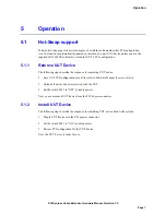
Perform hot swapping with a certain degree of carefulness. Remember that PCI configuration 
won’t be loaded or automatically updated on insertion of a new UUT device unless you use the 
supplied HOT SWAP software to reload the UUT’s PCI configuration. 

5.1.1 

Remove UUT Device 

The following steps describe the sequence for removing UUT device: 

1.


Save UUT PCI configuration into a file (refer to Software Manual for 

more details). 

2.


Unload all device drivers associated with the UUT. 

3.


Set the switch SW1 to “OFF” (disable power). 

Now, you can remove UUT device from the PCI Express connector. 

5.1.2 

Install UUT Device 

The following steps describe the sequence for installing UUT device back to the system: 

1.


Plug in UUT device into the PCI express connector. 

2.


Set the switch SW1 to “ON” (enable power). 

3.


Restore PCI configuration for the UUT device. 

Now, the UUT device is ready for use. 


Summary of Contents for PCI Express Cable Extender

Page 1: ...www amfeltec com Copyright 2012 Amfeltec Corp PCI Express Cable Extender Hardware Manual October 20 2012 Revision 1 2...

Page 2: ...atures 4 3 1 Power Interface Signals 4 3 2 Debugging Support 4 3 3 Software 5 4 Installation 6 4 1 Hardware 6 4 2 Software 6 5 Operation 7 5 1 Hot Swap support 7 5 1 1 Remove UUT Device 7 5 1 2 Instal...

Page 3: ...Cable Extender 2 Figure 2 PCI express interface board 3 Figure 3 ExpressCard interface board 3 Figure 4 PCI express stabilization tabs 5 Figure 5 Board layout 8 Tables Table 1 LEDs 9 Table 2 Switches...

Page 4: ......

Page 5: ...n this document is accurate and complete at time of release Please contact AMFELTEC Corp if you find any errors inconsistence or have trouble understanding any part of this document To provide your fe...

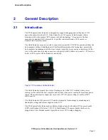
Page 6: ...at is new make it possible to move noisy computer out of the way At the same time by using connection via ExpressCard it allows to connect x1 PCI express board via PCI express Cable extender to any la...

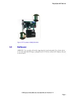
Page 7: ...owing components 1 PCI Express Cable Extender Figure 1 2 x1 PCI express interface board Figure 2 or ExpressCard interface board Figure 3 3 Data CAT6 cable and control flat cable 4 User manual 5 Extern...

Page 8: ...or for easy access to the PCI expresses JTAG signals Enable plug in JTAG emulators or AMFELTEC Easy Loader for programming loading CPLD FPGA on the UUT during testing production cycle Two pin ground j...

Page 9: ...ion 1 2 Page 5 Figure 4 PCI express stabilization tabs 3 3 Software AMFELTEC Corp provides software for supporting hot swap functionality The software allows to save and restore the PCI Express config...

Page 10: ...ard interface board and the other end to the connectors on the PCI Express Cable Extender In case that it is necessary to use external power supply for powering UUT the external power supply has to be...

Page 11: ...llowing steps describe the sequence for removing UUT device 1 Save UUT PCI configuration into a file refer to Software Manual for more details 2 Unload all device drivers associated with the UUT 3 Set...

Page 12: ...Hardware Description PCI Express Cable Extender Hardware Manual Revision 1 2 Page 8 6 Hardware Description 6 1 Board Layout Figure 5 Board layout...

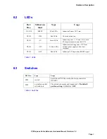
Page 13: ...3V and 12V on the PCI express connector on the UUT D3 D6 12V Yellow LEDs Indication incoming power 12V from external power supply or from host computer D7 D8 RST Red LEDs Indication PCI Express bus R...

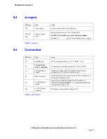
Page 14: ...sage J6 3 pin header PCI Express Bus power 3 3V GND 12V J1 2 1 mm Power Jack internal External power supply connection 12V 4A DC J5 2x5 right angel header 10 pin flat control cable for connection to t...

Page 15: ...Hardware Description PCI Express Cable Extender Hardware Manual Revision 1 2 Page 11 6 6 Power Limits Power Maximum current for Over voltage protection 3 3V 3 0A 12V 2 1A Table 5 Power Limits...

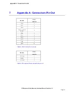
Page 16: ...1 2 Page 12 7 Appendix A Connectors Pin Out Function JTAG connector TCK 1 N C 2 TDO 3 Local 3 3 Volt output 4 TMS 5 N C 6 TRST 7 N C 8 TDI 9 GND 10 Table 6 JTAG connector J4 pin out Function JTAG conn...

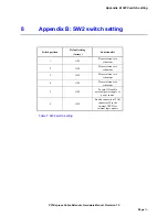
Page 17: ...etting factory Functionality 1 OFF Please reference to schematic 2 OFF Please reference to schematic 3 OFF Please reference to schematic 4 OFF Please reference to schematic 5 OFF In case ON enable ext...

Page 18: ...which would cause interruption of work or loss of profits such as shipboard or military attachment THIS LIMITED WARRANTY IS IN LIEU OF ALL OTHER WARRANTIES EXPRESSED OR IMPLIED THE WARRANTIES PROVIDE...

Reviews: