background image

Vision Research, Inc.  |  Phantom TMX Series Camera Manual

Chapter 2: Connectors  |  5

C

O

NNE

C

TO

R

S

B

3 STROBE /P

C

5 READY /P

D

2 TC IN

E

1 TRIGGER

F

4 FSYNC /P

H

RANGE DATA

G

6 TC OUT /P

I

REMOTE

J

BACKUP DC INPUT

K

PRIMARY DC INPUT

L

USB

M

ETHERNET

N

POWER SWITCH

O

CINEMAG PORT

A

SDI

P

VF POWER

Q

CAPTURE

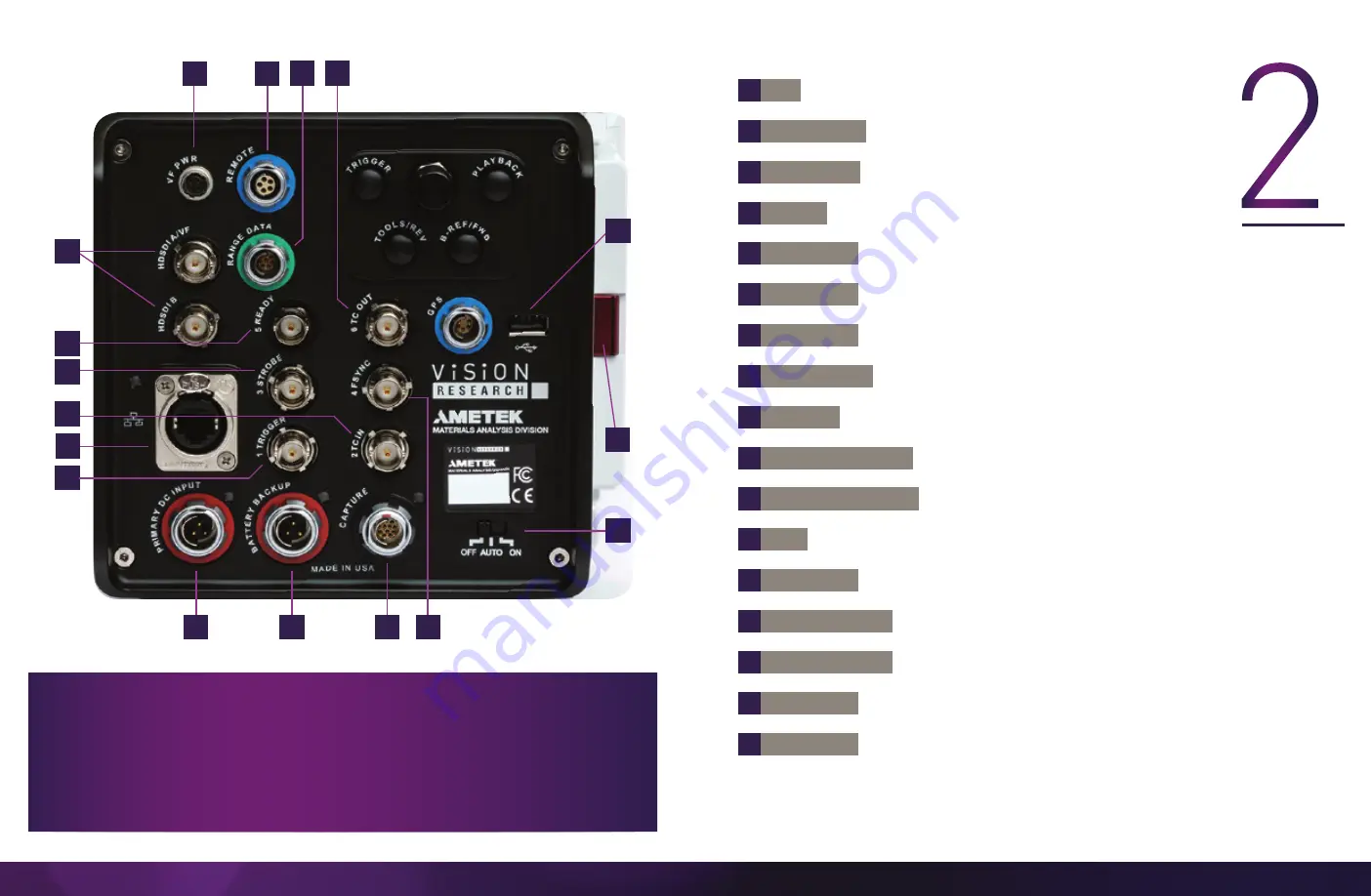
BNCs outputs 3G-SDI video


Programmable I/O, Port ID = P3. Default signal = Strobe


Programmable I/O, Port ID = P5. Default signal = Ready


Timecode-in fixed port for IRIG-B (Modulated/Unmodulated)


Trigger-in fixed port. TTL pulse, Switch closure


Programmable I/O, Port ID = P4. Default signal = FSync


Programmable I.O, Port ID = P6. Default signal = TC OUT


8-pin Fischer used to input and embed frames with acquisition data


5-pin Fischer for RS-232 serial communication


3-pin Fischer for 20-28V DC backup power


3-pin Fischer for 20-28V DC primary power

For WiFi dongle (Dongle requires chipset RT5370)


Ruggedized RJ45 for Gigabit and 10Gb Ethernet for control and data  


transfer


Off/Auto/On functionality (see FAQ)


Port on right side of camera, exists on CineMag models only


Power for Monitors


12-pin Fischer for signal access (Capture cable not included with camera)

A complete cable connector reference and pin-out 

guide is available in the last section of this manual.

M

N

P

E

B

C

A

H

G

I

D

F

J

Q

K

0

L

Summary of Contents for Phantom TMX 6410

Page 1: ...TMX 7510 6410 USER MANUAL When it s too fast to see and too important not to PHANTOM HIGH SPEED CAMERA ...

Page 2: ... Setup Quick Start Guide 7 4 On Camera Controls On Screen Display 13 5 Working with Phantom CineMag and CineStation 23 6 Phantom PCC Software 27 Camera Operation Playback and Downloading File Conversion 7 Signals and Programmable I O 37 8 Accessories 41 9 FAQs Support 43 Mechanical Drawings Connector Pin outs Regulatory When it s too fast to see and too important not to Phantom TMX 7510 6410 User ...

Page 3: ... 64 Gpx sec throughput CUTTING EDGE SENSOR TECHNOLOGY TMX cameras are the first high speed cameras that use a back side illuminated BSI sensor BSI technology places the metal required for high frame rates on the back of the sensor exposing the pixels to light This makes the sensors very light sensitive Additionally with BSI technology TMX cameras provide larger resolutions for very high frame rate...

Page 4: ...equirement to define the PC s dedicated camera network Automatic DHCP is an alternative to the secondary userdefinable IP network available in all Phantom cameras CAMERA CONTROL Phantom cameras come with PCC software for Ethernet based setup and control TMX cameras also have an On Camera Control OCC menu system for use with an attached video monitor The OCC menu can adjust both basic and advanced ...

Page 5: ...rt ID P4 Default signal FSync Programmable I O Port ID P6 Default signal TC OUT 8 pin Fischer used to input and embed frames with acquisition data 5 pin Fischer for RS 232 serial communication 3 pin Fischer for 20 28V DC backup power 3 pin Fischer for 20 28V DC primary power For WiFi dongle Dongle requires chipset RT5370 Ruggedized RJ45 for Gigabit and 10Gb Ethernet for control and data transfer O...

Page 6: ... versions of Windows 10 operating systems The latest version can be downloaded at www phantomhighspeed com PCC Gb 10Gb ETHERNET Phantom TMX Series cameras come with standard Gigabit Gb Ethernet and 10 Gigabit 10Gb Ethernet The camera has one Ethernet port which handles both protocols The camera will auto negotiate the connection speed based on the computer s network card and its IP configuration a...

Page 7: ... to the 172 16 IP range Use the Phantom NetConfig Utility as described in the previous section to detect the new network and assign the 10Gb IP address automatically Alternatively In the Windows Network and Sharing Center select the camera network Change the Ethernet IP settings by selecting Properties then TCP IPv4 Properties then select Use the following IP address Enter IP address 172 16 0 and ...

Page 8: ...ame F POWER ON CAMERA Connect the camera s dedicated power supply to the Primary DC input and move the power switch to the ON position The camera is ready for operation when the red capture light of the Trigger button is illuminated MOUNT PHANTOM CINEMAG OPTIONAL Insert a Phantom CineMag V if applicable For detailed instructions see Working with Phantom CineMag section LAUNCH PCC SOFTWARE Double c...

Page 9: ...lect Exit the menu by waiting 10 seconds or tapping the Trigger button Tap to enter playback mode when a cine is stored in RAM Playback buttons will glow green when camera is in playback mode In Live mode a tap of the Tools button will cycle through video zoom levels for focus assist and threshold exposure assist When in playback mode the play backward symbol is illuminated and this button is used...

Page 10: ...count and playback duration based on current video settings within the mark in and mark out points C BUFFER BAR WITH TRIGGER POINT D FRAME COUNT DURATION E FLASH MEMORY STATUS F EF LENS APERTURE DATA H CAPTURE SETTINGS K PLAYBACK BAR L PLAYBACK G CAMERA NAME I CINE INDICATOR B TIMECODE ON SCREEN DISPLAY OSD OVERVIEW The On Screen Display OSD provides valuable information about the camera s current...

Page 11: ...ternal to an external source AUTO B REF When enabled a black reference will be automatically performed when the camera enters Capture mode MENU OVERVIEW The On Camera Control menu provides access to major camera settings for operation and playback The menu is activated with a press of the menu knob and displayed as an overlay to the camera s video outputs HD SDI NAVIGATION Activate the menu by pre...

Page 12: ...ress of the camera User defined IP address secondary IP which can be set to AUTO for DHCP compatibility or used with a defined IP range outside of the Phantom 100 100 network This is set using Phantom PCC software 10 Gigabit 10Gb IP address of the camera as assigned by Vision Research 2 6 IMAGE The IMAGE page allows for control of image processing and video settings These image settings are adjust...

Page 13: ... not interrupt this saving process Once the save is complete the RAM can be cleared and the camera can go back into Capture mode The fastest way to do this is to hold down the Trigger button for four seconds P L A Y B A C K S A V E 5 6 AUTO The AUTO menu defines some of the camera s automatic functions AUTO TRIGGER Enables the camera s Image Based Auto Trigger IBAT function The settings for Size a...

Page 14: ...d out points prior to transfer from the RAM buffer to the CineMag Cine files are downloaded over Ethernet either 1Gb or 10Gb using Windows based Phantom PCC The CineMag V can be downloaded from the camera body or CineStation IV INSERTING A CINEMAG The Phantom CineMag slides into the top compartment of the camera and the door latches shut Ensure the CineMag slides in evenly and mounts securely Cine...

Page 15: ...the Cine pull down menu You will see all files in RAM as well as the Flash Cines in the CineMag in this list Once you ve selected a clip mark an in and out point if desired by clicking the and buttons respectively Phantom Video Player PVP can be used in a similar manner over video playback Then click the green Save Cine button choose Cine Raw as the file format navigate to the folder where you wis...

Page 16: ...pture parameters sample rate exposure time etc are performed in the Live tab Reviewing editing and saving of Cine files either from the camera s internal RAM memory installed Phantom CineMag V or external hard drive are performed in the Play tab The latest version of Phantom PCC software can be downloaded from the Vision Research website www phantomhighspeed com pcc This manual covers the most com...

Page 17: ...ult values and the Color Matrix Restore button returns the color matrix values to their default values Changes made here only affect the metadata of the Cine Raw file They are applied in software but not baked in Image Processing settings are no longer editable after saving to a format other than Cine Raw so it is important to ensure they are set to values that produce the best looking image PHANT...

Page 18: ...in Flash This feature saves a user specified portion of a clip to the Phantom CineMag immediately after recording Auto play Video Out Begins playback after recording The range marked under Auto play Video Out affects both playback and saving to the Phantom CineMag Restart Recording When enabled automatically restarts the recording process after the Auto actions have been performed IMAGE DISPLAY Th...

Page 19: ...rnal Camera uses its internal crystal oscillator to drive the frame rate External Camera uses externally supplied frame sync clock pulse to drive the frame rate This can be used to synchronize two cameras together via F Sync IRIG Camera uses an IRIG B signal is supplied to drive the frame rate Lock to Video Frame rate is driven by the camera s current video rate Fps will jump to the closest multip...

Page 20: ...e original Cine file EDITING AND SAVING A CINE Using the following Video Control buttons locate the first image of the Cine to be saved and click the Mark In button Locate the last image of the Cine to be saved and click the Mark Out button Click Play Speed Option and enable check Limit to Range Under the Video Control buttons click the play button and review the edited Cine Click the Save Cine bu...

Page 21: ...ferent signals the signal characteristics can be modified to better interface with external devices In most cases the signal polarity filter time delay pulse width and edge rising versus falling can be set Setting these characteristics is referred to as Pulse Processor Control Programmable I O ports are ports 3 through 6 Each port is to be identified in the PCC Camera Signals menu using the port n...

Page 22: ... in microseconds and is internally routed to pixel clock units Please note that pulse processors can sometimes generate pulses too short for the output drivers to switch and the processed signal should be verified with an oscilloscope before use PROGRAMMABLE SIGNALS DESCRIPTIONS The settings as described are the signal s default state prior to processing Ready An isolated open collector output wit...

Page 23: ... with the duration Software Trigger An active high output signal pulse generated as a result of the trigger protocol command Recording An active high output signal indicating active recording into a RAM partition Event In If the input is sampled low at the end of an exposure an E Event bit in the frame s timestamp is set Memory Gate In If the input is sampled low at the end of an exposure the corr...

Page 24: ...nctionality exists with a USB WiFi adapter attached to the camera s USB port The USB adapter must support 802 11 protocol and it must have an RT5370 chipset for compatibility Vision Research sells a compatible adapter with part VRI USB WIFI Ensure the adapter is installed when the camera boots up Once connected the WiFi Network will be visible as the camera name The password for the connection is ...

Page 25: ...Vision Research Inc Phantom TMX Series Camera Manual Chapter 9 FAQs Support 45 M E C H A N I C A L D R A W I N G S REAR VIEW LEFT RIGHT ...

Page 26: ... trigger pulse needs to be at least three microseconds long 2 TC In Dedicated I O Timecode In can accept IRIG B and SMPTE standards 3 F sync P ETHTXP 10 100 1000BA Programmable I O Default F Sync 5V maximum threshold input is also compatible with TTL levels and must be a properly terminated 50 ohms SE T Ethernet Transmit positive 4 Strobe P Programmable I O Default I O Strobe Isolated collector ou...

Page 27: ...S 422 5V maximum 5Mbps 60m max distance 6 3V3R 7 24VR 8 GND Power Ground REMOTE CONNECTOR FEMALE Cable 5 pin Fischer Part S 103 A 054 130 PIN NOMENCLATURE FUNCTION 1 24VDC output 2 PNG The power and the acquisition control signals are isolated from the camera system ground This isolation is designed to avoid system ground loops only and should not be subjected to high voltages 3 XRXD Receive Data ...

Page 28: ...backup mode How does the AUTO ON OFF switch work When a 20 28V power source is connected to the Backup DC only and the switch is set to AUTO the camera WILL NOT power up Connect power to the Primary DC input and the camera will power up In this situation if there is a loss of primary power then the backup power will be used to maintain camera operation and protect any stored data AUTO is required ...

Page 29: ...nc Wayne New Jersey 100 Dey Road Wayne New Jersey 07470 USA T 1 973 696 4500 For answers to most questions please visit us at www phantomhighspeed com and search the camera product pages tutorials support knowledgebase and FAQs SUBMITTING A SUPPORT TICKET For technical product support operation and application information or to request an RMA please submit a ticket by filling out a form at www pha...

Page 30: ...WWW PHANTOMHIGHSPEED COM 100 Dey Road Wayne NJ 07470 USA 1 973 696 4500 The contents of this manual are subject to change without notification PN ZDOC 64114 MA 0001 Rev 1 Last Updated March 2021 ...

Reviews: