


21
Note: All field-installed wiring must comply with NEC
and applicable local codes.
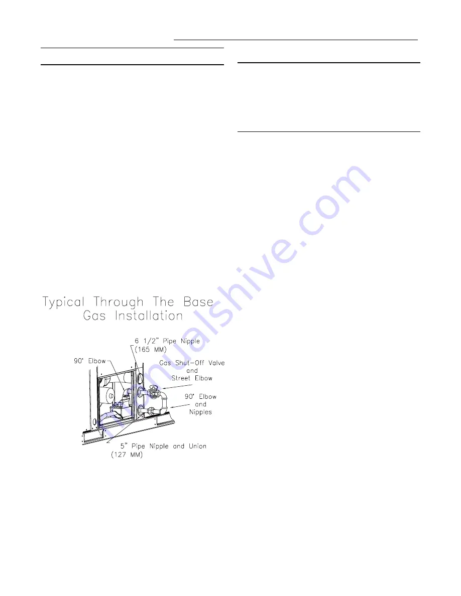
Through the Base Gas Installation
The gas supply line must extend 4-5/8" above the basepan.
The "Through the Base Gas kit" is located in the Heat Vesti-
bule compartment. To gain access to the kit, remove the
Heat Compartment access panel. Remove the pipe assem-
bly strapped to the manifold. Unscrew 90
°
elbow from 6 1/2"
nipple and slide rubber grommet off of nipple.
1. Remove the plastic plug from the hole in the center post
and insert the grommet removed from 6-1/2" pipe nipple.
2. Using pipe sealant, attach the 90° elbow to the gas sup-
ply line.
3. Disconnect the 5" pipe nipple and union from the
"Through the Base Gas kit assembly".
4. Using pipe sealant, attach the 6 1/2" nipple and gas
shutoff assembly to the 90° elbow on the gas supply line.
5. Using pipe sealant, attach the 5" pipe nipple and union to
the street el attached to the gas valve.
6. Connect 5" pipe nipple and union to 6 1/2" nipple and
gas shutoff assembly.
Continue to : "Requirements for Gas Heat Section"
Requirements for Gas Heat
Note: The unit gas train and Optional Through The
Base Gas Shut-Off Valve are rated at 1/2 PSIG
maximum. A pressure reducing regulator is
recommended to prevent this maximum from being
exceeded. These components must be isolated
during field gas piping test that exceed 1/2 PSIG. It is
recommended that the field piping be capped prior to
the unit gas train or Optional Through The Base Gas
Shut-Off Valve if present.
[ ] Gas supply line properly sized and connected to the unit
gas train.
[ ] All gas piping joints properly sealed.
[ ] Gas piping leak checked with a soap solution. If piping
connections to the unit are complete, do not pressurize
piping in excess of 0.50 psig or 14 " W.C. to prevent com-
ponent failure.
[ ] Drip leg Installed in the gas piping near the unit.
[ ] Minimum gas supply pressure should be 4.5" W.C.
[ ] Maximum gas supply pressure must not
exceed 14.0" W.C.
[ ] Manifold pressure for single stage heaters should be set
to 3.3" W.C.
[ ] Manifold pressure for two stage heaters should be set to
3.5" W.C. on HIGH FIRE and 1.8" W.C. on LOW FIRE.
[ ] Flue Exhaust clear of any obstruction.
Condensate Drain Configuration
An evaporator condensate drain connection is provided on
each unit. Refer to Figure 4-1 for the appropriate drain loca-
tion.
The condensate drain pan is factory installed to drain con-
densate to the back side of the unit. See Figure 4-1. It can
be converted to drain condensate out the front side of the
unit or through the base.
To convert drain condensate out the front of unit:
1. Remove evaporator access panel and supply air access
panels.
2. Remove the support panel that the condensate drain pan
exits through.
3. Slide the condensate drain pan out of the unit and rotate
180°.
4. Slide the condensate drain pan back into the unit, align
the drain with the grommeted opening in the rear support
panel and push until the coupling is seated in the grom-
met.
5. Replace the front support panel by aligning the panel
with tabs in the raceway. Align the condensate drain pan
support in the grommeted hole as the panel is put in
place.
Installation