background image

Summary of Contents for ADXIB040A9241A

Page 1: ...1A __First letter may be A or T ALL phases of this installation must comply with NATIONAL STATE AND LOCAL CODES DXIB040A9241A DXIB060A9361A DXIB080A9421A DXIC100A9481A DXID120A9601A IMPORTANT This Document is customer property and is to remain with this unit Please return to service information pack upon completion of work UX 1 DX 1 A R FLOW UPFLOW DOWNFLOW AIR FLOW AIR FLOW U PFLOW HORIZONTAL DOW...

Page 2: ...ructions Safety signal words are used to designate a degree or level of seriousness associated with a particular hazard The signal words lbr salety markings are DANGER WARNING and CAUTION a DANGER indicates an imminently hazardous situation which if not avoided will result in death or serious injury This signal word is limited to the most extreme situa tions CARBON MONOXIDE POISONING HAZARD Failur...

Page 3: ...ler s Guide Contents INSTALLATION INSTRUCTIONS General Installation Instructions Location and Clearances Outline Drawings Upflow Installation Downflow Installation Horizontal Installation Air For Combustion and Ventilation Duct Connections Return Air Filters General Venting Instructions Venting Material Venting Tables Horizontal Venting Venting Through The Wall Venting Throught The Roof Downward V...

Page 4: ... D TO 2 I 2 OR 3 ON SOME MODELS AT Di_LRENT ALTii_D S REFER _0 T_ VENT LF GTH TA LE _OR PROPER APPLICA_iON SEE NoTEMODELI 2 DIM A DIM B DIM C DIM 3 DIM E DIM F _UX i BO4OAgP I i A _ UXi5060A936i _UX iBO80A942i _ UXO60R936 _ _UX080 942_ _ _UYOGQRgVS_ _UYO8OR9V3_ _UX 5040A9 21 _UX BO60A963 _ UX BOSOAgN3 i7 i 2 2 i 4 i6 i 4 16 7 1 2 _ UXiG i 00A948i _ UX iC080A960 i _UX i00R948 _ UY OORf V4_ _ _UX i ...

Page 5: ...T R OF VFN PIPE ray BF _ qlFD 0 2 i _ OR 3 ON S E MOO LS AT DIRR R f _L TUOES REFER TO THE V S T L fsq TH T _ _LE FOr7 _70PER APPLfCATiON MODEL A B C D DX1 B040A9241A DX1B060A9361A 17 1 2 2 1 4 16 1 4 16 DX1 B080A9421A DX1C100A9481A 21 2 1 2 19 3 4 19 1 2 DX1D120A9601A 24 1 2 2 15 16 23 1 4 23 First letter may be A or T MINIMUM CLEARANCETO COMBUSTIBLEMATERIALS DOWNFLOW SIDES O _EAR O RONT 3 N OP U...

Page 6: ... brackets with screws are included with downflow furnaces for installation to stabilize and secure the furnace and TXC cased coil in the horizontal position See Figure 4 The coil is placed downstream of the furnace with the apex of the coil pointing in the direction of the airflow lor horizontal installation The cased coil is secured to the furnace and both the furnace and the cased coil must be p...

Page 7: ...waxes and cleaners Chlorine based swimming pool chemicals Water sol_ening chemicals Deicing salts or chemicals Carbon Tetrachloride Halogen type reli igerants Cleaning solvents such as perchloroethylene Printing inks paint removers varnish etc Hydrochloric acid Cements and glues Antistatic fabric softeners for clothes dryers Installer s Guide Masonry acid washing materials Furnace locations may be...

Page 8: ...ize noise transmission through the return air grille Although these filrnaces are designed with large blowers operating at moderate speeds any blower moving a high w lume of air will produce audible noise which could be objectionable when the unit is located very close to a living area It is often advisable to route the return air ducts under the floor or through the attic Such design permits the ...

Page 9: ...t side return air inlet TABLE 3 MODELS CABINET RLTER NUMBERS WIDTH QTY SIZE UX1B040A9241A UX1B060A9361A 17 1 2 1 17 X 25 X 1 UX1B080A9421A UX1C080A9601A 21 1 20 X25 X 1 UX1C100A9481A UX1D100A9601A 24 1 2 1 24 X25 X 1 UX1D120A9601A Firstlettermaybe A or T NOTE On 5tonairflow models iftheairflow requirement exceeds 1800CFM thesemodels willrequire filtersonbothsides OR1sideandthebottom ORjustthebotto...

Page 10: ... the upper retaining pin screw locks into the engagement hole in the blower deck and the lower pin screw rests against the side of the bottom panel See Figures 14 18 d Install the optional fllrnace filter on the side inserting the chamler end first Filter Furnace Rack Cabinet Side Engagement Hole For Filter Rack Installation With Bottom Return Filter Rack Retaining Screw Pin BOTTOM ENGAGEMENT Furn...

Page 11: ...g door the blower door hinge may be removed without creating any problems with the seal of the furnace To remove the blower door tilt the door Iorward 2 to 3 inches anti pull up To remove the tilt feature simply remove the lower hinge as shown in Figure 21 The bottom of the blower door will catch in the bottom of the l_lrnace front channel for door replace ment Door Hinge Removed ALTERNATE UPFLOW ...

Page 12: ...ion of the filter retaining brackets shipped with downflow furnaces TABLE 4 MODELS CABINET FILTER NUMBERS WIDTH QTY SIZE DX1B040A9241A DX1B060A9361A 17 1 2 2 14 X20 X 1 DX1B080A9421A DX1C100A9481A 21 2 16 X 20 X 1 DX1D120A9601A 24 1 2 2 16 X20 X 1 First letter may be A or T TABLE 5 LOCATING FILTER RETAINER BRACKETS IN DUCTWORK CABINET RETURN DIMENSION DIMENSION FILTER DUCT BRACKET WIDTH WIDTH A B ...

Page 13: ...eing inspected in operation Adjust thermostat so appliance will operate continuously 5 Test lbr spillage at the draR hood relief opening alter 5 minutes of main burner operation Use the flame of a match or candle or smoke from a cigarette cigar or pipe 6 Alter it has been determined that each appliance remaining connected to the common venting system properly vents when tested as outlined above re...

Page 14: ...heavy coat of cement to the pipe end and insert pipe into fitting with a slight twisting movement until it bottoms out 4 Hold the pipe in the fitting lot 30 seconds to prevent tapered socket from pushing the pipe out of the fitting 5 Wipe all excess cement from the joint with a rag Allow 15 minutes belore handling Cure time varies according to fit temperature and humidity NOTE Follow venting instr...

Page 15: ...30AVENTA or BAYVENT200 without additional length restriction DOWNFLOW HORIZONTAL VENTING TABLE TABLE 9 MAXIMUM VENT LENGTH DIRECT VENT 2 PIPE SYSTEM NONDIRECT VENT 1 PIPE SYSTEM MAXIMUM TOTAL EQUIVALENT FEET FOR MAXIMUM TOTAL EQUIVALENT FEET FOR VENT AND INLET AIR PIPES See Notes VENT PIPE ONLY See Notes 2 PIPE 2 1 2 PIPE 3 PIPE 4 PIPE 2 PIPE 2 1 2 PIPE 3 PIPE 4 PIPE MODEL FITTINGS FITTINGS FITTIN...

Page 16: ...let 3 feet 91 cm 6 inches 15 cm for appliances 10 000 Btuh 3 kw 12 6 inches 15 cm for appliances 10 000 Btuh 3 kw 9 j Clearance to nonmechanical air supply inlet to building inches 30 cm for appliances 10 000 Btuh 3 kw and inches 23 cm for appliances 10 000 Btuh 3 kw and or the combustion air inlet to any other appliance 100 000 Btuh 30 kw 36 inches 91 cm for appliances 50 000 Btuh 15 kw 12 inches...

Page 17: ...cal air supply inlet to building inches 30 cm for appliances 10 000 Btuh 3 kw and 4 feet 1 2 m below or to side of opening 1 foot 300 m above or the combustion air inlet to any other appliance 100 000 Btuh 30 kw 36 inches 91 cm for appliances opening 100 000 Btuh 30 kw K Clearance to a mechanical air supply inlet 6 feet 1 83m 3 feet 91 cm above if within 10 feet 3m horizontally Clearance above a p...

Page 18: ...k to the fllrnace FLUE GAS DEGRADATION The moisture content of the title gas may have a detrimental efl ect on some building materials This can be avoided by using the roof or chimney venting option When wall venting is used on any surlhce that can be affected by this moisture it is recommended that a corrosion resistant shield 24 inches square be used behind the vent terminal This shieM can be wo...

Page 19: ...LOVff FURNACE HORIZONTAL AND VERTICAL VERTICAL J NOTE VENT AND INLET MUST BE SUPPORTED _ SEE VENTING TABLE _ ATA MAXIMUM OF 3 INTERVALS STRAPS OR OTHER SUITABLE SUPPORTS _ AT MAXIMUM OF 3 0 INTERVALS AUsEONLY I _ TERMINATIOt_ n COM_US ON _ F 9 l _ il _x _UPWARD PITCH 1 4 PER FOOT l_ I I I F RoSTESUoPPFOuRTNASHEOUL BEEASoN_ _ AS POSSIBLE O UwT _ LD E 40 UPFLOW OR DOWNFLOW MODELS 45 ELBOW OUTSIDE WA...

Page 20: ...ght seal Lubricate flexible seal on flashing befl re PVC pipe is pushed through the seal Field Supplied NOTE No vent cap as shown in Figure 35 is the preferred method for vertical vent termination in extremely cold climates In extreme climate conditions insulate the exposed pipe above the roof line with Armaflex type insulation VENTING ROUTED THROUGH A MASONRY CHIMNEY VENT FITTING MATERIAL STAINLE...

Page 21: ... flue pipe joints must be sealed The 90 elbow connection to vertical pipe must be sealed to prevent condensate leakage to base of masonry chimney Installer s Guide WITH HI TEMP RTV SILICONE SEALANT J CLEARANCE 0 ACCEPTABLE FOR PVC VENT PIPE 1 ACCEPTABLE FOR TYPE 29 4C STAINLESS STEEL VENT PIPE VENTING THROUGH CEILING PVC PLASTIC VENTING ONLY THROUGH UNUSED CHIMNEY STAINLESSSTEEL VENTCAP OPTIONAL F...

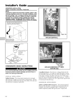
Page 22: ...recommended that a drain pan be installed under the furnace to prevent property damage personal injury or death from leaking condensate VERTICAL APPLICATIONS Upflow furnace I The connection tubing lbr left and right side drainage is shipped in the blower compartment Install the connection tubing from the trap to the side of the unit and trim all excess tubing to aw_id kinks Use Inducer Drain hose ...

Page 23: ... need to be cut to fit between the inducer and the trap On upflow units this tube may need to be extended using the tubing shipped with the furnace Connections must be made to an OPEN VENTED DRAIN Outdoor draining of the furnace and coil condensate is permissible if allowed by local codes Caution should be taken to prevent drains from freezing or causing slippery conditions that could lead to pers...

Page 24: ... OR PR UNT _ R NG DIAGRAM H SE ADS PNOV E 5 V POWER ON CONNF I ON O E E IRON C C AN _ AND HUMID IE qAX lOAD 0 _ PS ACH i lS CO_ _N CI ON S ON Y USeD O I Rvos AiS REQU P NG CON _ECi 10N 10 il 24 V P0Wl SiP _ Y 0V_ ION S _ _ 1 i_ COV i I 0N D A ilisYS 0 P 0P R CON_ iC 0NS WE JSIk i TI S FLATURE From drawing B341437 Rv 1 OUTDOORUNIT NO TRANSFOR ER FIELD WIRING DIAGRAM FOR 1 STAGE FURNACE 1 STAGE HEAT...

Page 25: ...NALS FRO_a TWInCONNECTION SEE NOTE 4 l RI _ i SEE NOTE 4 80TH FU_A4 ES _ T _E PO ERED FRO_r i 54 i _V 0 C I U T PM NSURF 24Y FURNACf 7RA SFOR_ ER ARE PHA PRIOR 0 CO LTIt 6 OtG ON _ CHECK i OL T46E rjEDI EE J R TERMINALS OF E4C1i F dfiN4C i_ vOL 74 _F i_ 6RLA_R i_iAti iOV I _V_RS_ iH_ 8L A f RB 5_ro t94RY i_A_S OR ONE OF THE Fd NACE T 4 S_OR_RS CONtCLCiI0tV AI t_ iOi l OR ELECTRONIC THFR_OSTAT iF C...

Page 26: ...ion drip leg to be installed ahead of the controls as shown in Figures 46 48 The fllrnace and its individual shut off valve must be discon nected from the gas supply piping system during any pressure testing of that system at test pressures in excess of 1 2 psig 3 5 kPa The fllrnace must be isolated from the gas supply piping by closing its individual manual shut off valve during any pressure test...

Page 27: ...ceed the nameplate rating Changes can be made by adjusting the manifold pressure or changing orifices orifice change may not always be required To adjust the manifold pressure a Turn off all electrical power to the system b Attach a manifold pressure gauge to the outlet pressure tap marked OUT PRESS TAP on White Rodgers gas valve model 36F or boss marked OUT P on White Rodgers gas valve model 36G ...

Page 28: ...ition to the regular gas valve pressure tap on the outlet side of the gas valve See Figure 49 Replace manifold pressure tap threaded plug and leak check after checking adjusting manifold gas pressure Table 11 lists the main burner orifices used with the fllrnace If a change of orifices is required to correct the fllrnace input rating reler to Table 14 TABLE 12 FINAL MANIFOLD PRESSURE SETTINGS FUEL...

Page 29: ...equired At Other Elevations 2000 3000 4000 5000 6000 7000 8000 9000 10000 42 43 43 43 44 44 45 46 47 44 44 44 45 45 46 47 47 48 45 45 45 46 47 47 48 48 50 46 47 47 47 48 48 49 49 50 47 47 47 48 48 49 49 50 51 48 48 49 49 49 50 50 51 52 54 54 55 55 55 55 55 56 56 56 55 55 55 55 56 56 56 56 56 57 56 56 56 57 57 57 58 59 59 60 57 58 59 59 60 60 61 62 63 63 58 59 60 60 61 62 62 63 63 64 From National ...

Page 30: ...arrange to have someone inspect your house for proper temperature This is very important during freezing weather If for any reason your furnace should fail to operate damage could result such as frozen water pipes SEQUENCE OF OPERATION Thermostat call for heat R and W thermostat contacts close signaling the control module to run its sell check routine Alter the control module has verified that the...

Page 31: ... power off then on then off and then on again within 30 seconds This may be done at the unit s power source or at the thermostat The system will not t e set unless the 19rc_edut o off on off on is comlglered within 30 seconds 8 RESET AFTER BURNER BOX LIMIT SHUTDOWN If the flwnace shuts down one thing that can be checked is the burner box temperature limit switch It is located on the bottom of the ...

Page 32: ...AC power reversed poor grounding or system voltage too low 7 Flashes Gas valve circuit error 8 Flashes Low flame sense signal Check Ignitor Circuit and Line N to 24VAC Common voltage _ 2 volts 9 Flashes possible grounding problem American Standard Inc 6200 Troup Highway Tyler TX 75707 Literature Order Number File Number Supersedes Stocking Location 18 CD 19D6 27 18 CD1 D6 27 08 06 18 CD 19D6 26 PI...

Reviews: