background image

StorTrends® 3100 User’s Guide 

62 


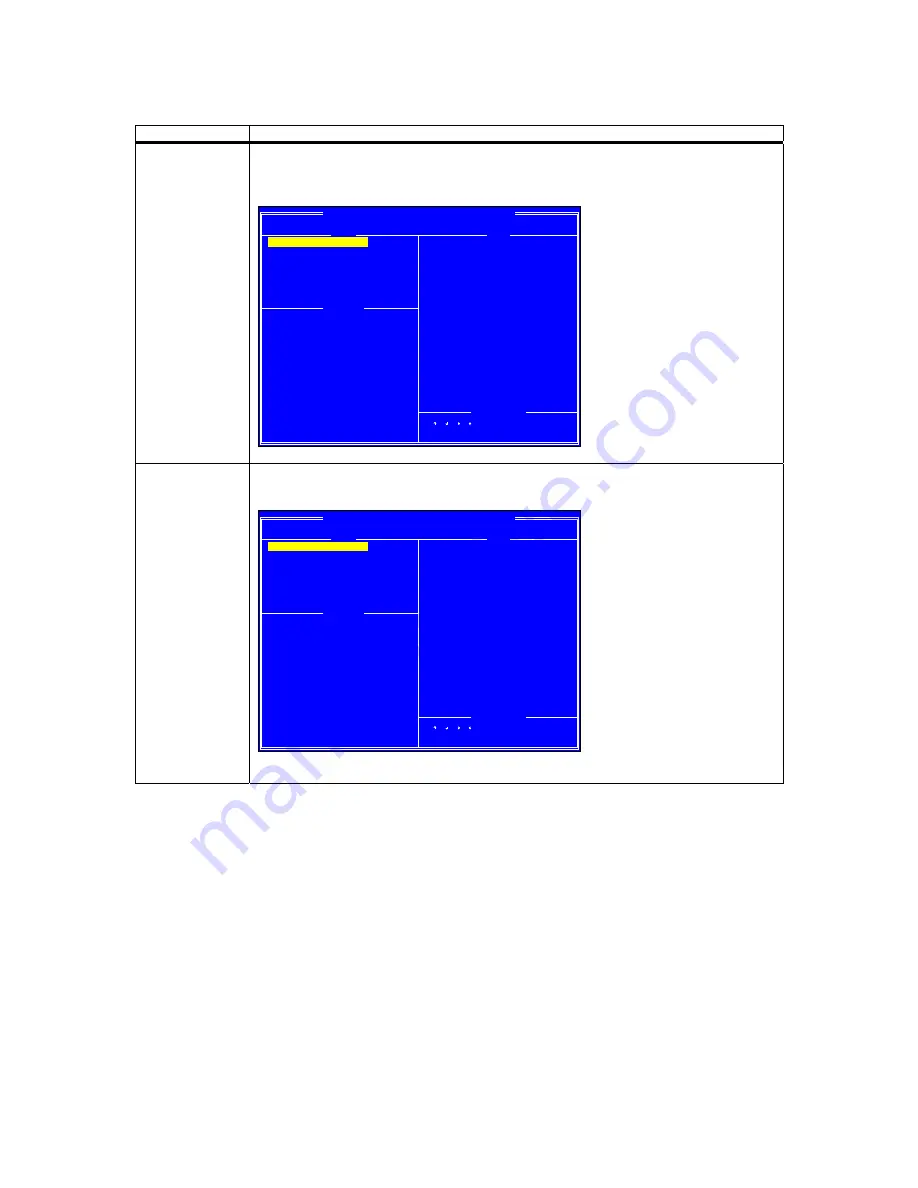
Step Description 

The first array in the 

Arrays

 list will become highlighted. The 

Disks

 list will display all disks 

involved in the selected array in green. Press the <A> key to select all the arrays in the 

Array


list. 
 

BC4852 Array Configuration (Build: xx-xxx-xxxxxxx.x)

1 - RAID50, 3.9GB, (no array name), Normal, Cache: R, DOS=3.6GB

1 - RAID50, 3.9GB, Normal

2 -- RAIDXX, XXXX, Critical

0-00-XXXGB-InArray
1-01-XXXGB-InArray
2-02-XXXGB-InArray
3-03-XXXGB-InArray
4-04-XXXGB-InArray
5-05-XXXGB-InArray
6-06-XXXGB-InArray
7-07-XXXGB-InArray
8-10-XXXGB-InArray
9-11-XXXGB-InArray
A-12-XXXGB-InArray
B-13-XXXGB-InArray
C-14-XXXGB-InArray
D-15-XXXGB-InArray
E-16-XXXGB-InArray

< >< >< >< >=Choose, <Esc>=Back
<Ins>=Select, <A>=All, <Enter>=Done

Initialize Disk(s)
Create Array

Delete Array(s)
Swap Two Arrays
Hide/un-Hide Array(s)
View Disk Details
View Array Details
Rescan All Channels
Controller Options
Continue to Boot

Arrays

Main Menu

Controllers Found: 2

Disks

Available Keys


All the selected 

Arrays

 will become highlighted in green along with all the disks in the 

Disks


list. 
 

BC4852 Array Configuration (Build: xx-xxx-xxxxxxx.x)

1 - RAID50, 3.9GB, (no array name), Normal, Cache: R, DOS=3.6GB

1 - RAID50, 3.9GB, Normal
2 -- RAIDXX, XXXX, Critical

0-00-XXXGB-InArray
1-01-XXXGB-InArray
2-02-XXXGB-InArray
3-03-XXXGB-InArray
4-04-XXXGB-InArray
5-05-XXXGB-InArray
6-06-XXXGB-InArray
7-07-XXXGB-InArray
8-10-XXXGB-InArray
9-11-XXXGB-InArray
A-12-XXXGB-InArray
B-13-XXXGB-InArray
C-14-XXXGB-InArray
D-15-XXXGB-InArray
E-16-XXXGB-InArray

< >< >< >< >=Choose, <Esc>=Back
<Ins>=Select, <A>=All, <Enter>=Done

Initialize Disk(s)
Create Array

Delete Array(s)
Swap Two Arrays
Hide/un-Hide Array(s)
View Disk Details
View Array Details
Rescan All Channels
Controller Options
Continue to Boot

Arrays

Main Menu

Controllers Found: 2

Disks

Available Keys


Press the <ENTER> key to continue. 

Summary of Contents for StorTrends 3100

Page 1: ...StorTrends 3100 User s Guide MAN 3100 07 31 06 ...

Page 2: ...ted in any form whatsoever without the prior written consent of the publisher American Megatrends Inc acknowledges the following trademarks All trademarks and trade names used in this document refer to either the entities claiming the marks and names or their products American Megatrends Inc disclaims any proprietary interest in trademarks and trade names other than its own Revision History 02 15 ...

Page 3: ...pset Overview 3 General Block Diagram 4 Chapter 2 Server Installation 5 Overview 5 Unpacking the StorTrends 3100 5 Preparing for Setup 5 Choosing a Setup Location 6 Rack Mounting Considerations 6 Chassis Front Panel View 7 Chassis Front Panel View 7 Button and LED Location 7 Button and LEDs Descriptions 7 Chassis Rear and Back Panel Views 8 Chassis Rear View 8 Back Panel View 8 Chassis Rear and Ba...

Page 4: ... the Chassis Cover 25 Reinstalling the Chassis Covers 25 Before Installing the Chassis into a Rack 26 Packing List and the Chassis Specifications 27 Chassis Contents 27 Accessory Box Contents 27 Rail Packing Contents 27 Power Supply Specifications 27 Serial ATA Back Panel 28 Jumper Settings Location 28 Chapter 5 Advanced Motherboard Setup 29 Overview 29 Handling the Motherboard 29 Precautions 29 U...

Page 5: ... Front Panel Universal Serial Bus Header 39 USB2 3 Pin Definitions 39 USB4 Pin Definitions 39 Serial Ports 40 Serial Port Pin Definitions COM1 COM2 40 GLAN1 2 Ethernet Ports 40 ATX PS 2 Keyboard and PS 2 Mouse Ports 40 PS 2 Keyboard and Mouse Port Pin Definitions J9 40 Fan Headers 41 4 pin Fan Header Pin Definitions 41 Power LED Speaker 41 Speaker Connector Pin Definition 41 Wake On Ring 41 Wake O...

Page 6: ...e Top Cover of the StorTrends 3100Chassis 50 Procedures 50 Accessing the Front Chassis Fans 51 Procedures 51 Accessing the Rear Chassis Fans 52 Procedures 52 Accessing the 760W Power Supply 53 Procedures 53 Installing the Air Shrouds 55 Installing the Small Air Shroud 56 Procedures 56 Installing the Large Air Shroud 57 Procedures 57 Appendix A StorTrends iTX Software Installation 59 Reinstallation...

Page 7: ...hased directly from AMI or from an AMI authorized reseller only If Then You purchased this product from AMI or from a certified AMI reseller Call AMI technical support at 770 246 8645 Please be prepared to specify the serial number of the product This AMI product was installed as part of a system manufactured by a company other than AMI or you purchased an AMI product from an unauthorized reseller...

Page 8: ...ose Some states do not allow disclaimer of express or implied warranties or the limitation or exclusion of liability for indirect special exemplary incidental or consequential damages in certain transactions therefore this statement may not apply to you Also you may have other rights that vary from jurisdiction to jurisdiction This publication could include technical inaccuracies or typographical ...

Page 9: ...vide reasonable protection against harmful interference in a residential installation This equipment generates uses and can radiate radio frequency energy and if not installed and used in accordance with the instructions may cause harmful interference to radio communications However there is no guarantee that interference will not occur in a particular installation If this equipment does cause har...

Page 10: ...al for their installation Chapter 3 System Interface Refer to this chapter for details on the system interface which includes the functions and information provided by the control panel on the chassis as well as other LEDs located throughout the system Chapter 4 System Safety You should thoroughly familiarize yourself with this chapter for a general overview of safety precautions that should be fo...

Page 11: ...oring Onboard voltage monitors for CPU cores chipset voltage 3 3V 5V 12V and 3 3V standby Fan status monitor with firmware software on off control CPU chassis temperature monitors Environmental temperature monitor and control CPU fan auto off in sleep mode CPU slow down on temperature overheat CPU thermal trip support for processor protection 5V standby alert LED Power up mode control for recovery...

Page 12: ...s w RAID0 RAID1 JBOD support 1 floppy port interface 2 serial ports 1 EPP ECP Parallel Port PS 2 mouse and PS 2 keyboard ports Up to 5 USB 2 0 Universal Serial Bus 2 ports 3 Headers Super I O Other Internal external modem ring on Wake on LAN WOL Console redirection Onboard Fan Speed Control by Thermal Management via BIOS Dimensions ATX Ext 12 x 13 05 304 8 x 331 5 mm ...

Page 13: ...ss interfaces These interfaces support connection of the MCH to a variety of other bridges that are compliant with the PCI Express Interface Specification Rev 1 0a The MCH interfaces with the 82801ER I O Controller Hub 5 R ICH5R via a dedicated Hub Interface supporting a peak bandwidth of 266 MB s using a x4 base clock of 66 MHz The PXH provide connection between a PCI Express interface and two in...

Page 14: ...CI X 100MHz J14 J14 J12 J12 ANVIK ANVIK 1 PCI EXP 1 PCI EXP SLOT SLOT J17 J17 PCI E B X8 PCI E B X8 PCI E C X8 PCI E C X8 J15 J15 1 PCI E 1 PCI E SLOT SLOT 1 PCI E 1 PCI E J16 J16 SLOT SLOT 4 DIMMs 4 DIMMs IDE IDE PRI SEC PRI SEC UDMA 100 UDMA 100 VGA VGA X4 X4 X4 X4 4 DIMMs 4 DIMMs 0 1 0 1 SATA SATA SATA SATA LPC BUS LPC BUS USB USB USB PORT USB PORT 0 1 2 3 4 5 0 1 2 3 4 5 BMC CON BMC CON LPCS I...

Page 15: ...with the carrier who delivered it Decide on a suitable location for the rack unit that will hold the StorTrends 3100 It should be situated in a clean dust free area that is well ventilated Avoid areas where heat electrical noise and electromagnetic fields are generated You will also need it placed near a grounded power outlet Read the Rack and Server Precautions in the next section Preparing for S...

Page 16: ...ATA drive to cool before touching them Always keep the rack s front door and all panels and components on the servers closed when not servicing to maintain proper cooling Rack Mounting Considerations Feature Description Ambient Operating Temperature If installed in a closed or multi unit rack assembly the ambient operating temperature of the rack environment may be greater than the ambient tempera...

Page 17: ...n D Power Indicator E LAN Activity LED F Overheat LED G System Alert Power Failure Warning LED Button and LEDs Descriptions LED Color Condition Description Power LED Green On System On Off System Off HDD LED Amber On HDD Activity Off No Activity LAN Activity LED Green On Linked Blink LAN Activity Off Disconnected Overheat LED Red On System Overheat Off System Normal System Alert Power Failure Warn...

Page 18: ...ations Location Name A Power Supply Modules 3 B Back Panel I O Ports C Rear System Fans D Full size PCI Expansion Slots 6 E Keyboard Mouse F USB Ports G COM Video Ports H LAN1 LAN2 I Parallel Port Power Module LED Description LED Color Condition Description Power Module LED Green Power Supply DC On Amber Power Supply Standby Off No AC Power to the system ...

Page 19: ... mm 0 197 C Thumb screw 6 32 x 5 mm 0 197 Drive Screws Screw Letter Description B Flat head 6 32 x 5 mm 0 197 D Pan head 6 32 x 5 mm 0 197 E Round head M3 x 5 mm 0 197 Rail Screws Screw Letter Description F Flat head M4 x 4 mm 0 157 G Round head M4 x 4 mm 0 157 H Flat head M5 x 12 mm 0 472 I Washer for M5 ...

Page 20: ...1 Turn off all peripheral devices and turn off the power supply connected to the chassis 2 Unplug all power cords from the system or the wall outlets 3 Disconnect all the cables and label the cables for easy identification 4 Use a grounded wrist strap designed to prevent static discharge when handling components Removing the chassis covers After completing the steps above you can remove the chassi...

Page 21: ...A drive tray from the chassis Procedures 1 Press the release tab located on the drive tray door to release the drive tray from its locking position as shown below 1 2a 2b 2 Pull the drive tray door upward and then pull the SCA drive tray out from the chassis 3 Mount a hard drive in the drive tray and make sure that all the screws are securely fastened 3a 3b ...

Page 22: ... Unplug the AC power cord s 3 Remove all external devices and connectors Procedures to Install Chassis Rails Included in the shipping package are a pair of rail assemblies In each rail assembly locate the inner rail and the outer rail Press the locking tab to release the inner rail from its locking position and pull out the inner rail from the rail assembly The inner rails are to be attached to th...

Page 23: ...3 4 Align the larger end of each hole against its corresponding button Once all aligned push the holes toward their corresponding buttons and the rail is placed on the chassis Once the rail is placed on the chassis pull the rail forward until the rail buttons lock in the small ends of the corresponding holes Secure the rail to the chassis with a Type G screw Repeat the above steps to install other...

Page 24: ...d rear long brackets Please note that the brackets are marked with Up Front Arrows front and Up Rear arrows rear 2 Secure the front short bracket marked with the Up Front arrows to the outer rail with two Type G screws 3 Locate the two buttons on the outer rail and attach the rear long bracket to it by sliding the opening of the rear rail through the button 4 Measure the depth of your rack and adj...

Page 25: ...Chapter Two Server Installation 15 6 Secure both outer rail assemblies to the rack with Type H screws and Type I Washers H I ...

Page 26: ...ly installed on the rack slide the StorTrends 3100into the assemblies as shown below Note The StorTrends 3100may not slide into the rack smoothly or easily when installed the first time However some adjustment to the slide assemblies might be needed for easy installation ...

Page 27: ...Chapter Two Server Installation 17 8 Secure the StorTrends 3100on the rack by tightening the screws on the front sides of the StorTrends 3100as shown below TIGHT TIGHT ...

Page 28: ...StorTrends 3100 User s Guide 18 ...

Page 29: ...f press the Alarm Reset button to reactivate the function D Power Indicator Indicates power is being supplied to the system s power supply units This LED should normally be illuminated when the system is operating E LAN Activity LED Indicates network activity when flashing F Overheat LED Indicates an overheat condition in the chassis This may be caused by cables obstructing the airflow in the syst...

Page 30: ...ivity Off Disconnected Overheat LED Red On System Overheat Off System Normal System Alert Power Failure Warning LED Red On 1 or more power module failures Off System Normal Serial ATA Drive Carrier LEDs On the front of each Serial ATA drive carrier is a green LED When illuminated it indicates drive activity A connection to the Serial ATA backplane enables this LED to blink on and off when that par...

Page 31: ...cations Location Name A Power Supply Modules 3 B Back Panel I O Ports C Rear System Fans D Full size PCI Expansion Slots 6 E Keyboard Mouse F USB Ports G COM Video Ports H LAN1 LAN2 I Parallel Port Power Module LED Description LED Color Condition Description Power Module LED Green Power Supply DC On Amber Power Supply Standby Off No AC Power to the system ...

Page 32: ...StorTrends 3100 User s Guide 22 ...

Page 33: ...to the system or injury to yourself Be aware of the locations of the power switches on the chassis and in the room so you can disconnect the power supply if an accident occurs Take extra precautionary measures when working with high voltage components It is not recommended to work alone Before removing or installing main system components be sure to disconnect the power first Turn off the system b...

Page 34: ...ic Static Discharge ESD can damage electronic components To prevent damage to your system board it is important to handle it very carefully The following measures are generally sufficient to protect your equipment from ESD Use a grounded wrist strap designed to prevent static discharge Keep all components and printed circuit boards PCBs in their antistatic bags until ready for use Touch a grounded...

Page 35: ...completing the above steps you can remove the covers and install components peripheral devices into the chassis as described in this user s guide 1 Unlock and remove the screws and fasteners to remove the cover or components 2 Save all the screws and fasteners for later use If necessary label these screws or fasteners for easy identification 3 Follow the instruction given in this user s guide to r...

Page 36: ...sis into the rack 3 Make sure that the system is adequately supported Make sure that all the components are securely fastened to the chassis to prevent components falling off from the chassis 4 Be sure to install an AC Power Disconnect for the entire rack assembly and this Power Disconnect must be clearly marked 5 The rack assembly shall be properly grounded to avoid electric shock 6 The rack asse...

Page 37: ...Cords 3 HDD Screws 1 SATA Cable 4 to 15 depending on your order configuration SATA LED Cable 2 Rail Packing Contents Component Quantity Rack Rail Assembly 2 sets Front Brackets for Mounting Rack Rail 2 Rear Brackets for Mounting Rack Rail 2 Mounting Screws 1 set Power Supply Specifications Specification Value Rated AC input voltage 100 240V AC Rated input frequency 50 60 Hz Rated input current 14A...

Page 38: ...2 Enabled H JP63 Closed Fan 3 Enabled I JP64 Closed Fan 4 Enabled Note Press the button on the front panel once to disable the buzzer If the buzzer has been disabled press the button again to re enable the buzzer Jumper Settings Location A C F B G H E D I Fan 1 Fan 2 Fan 3 Fan 4 Note By default we connect four chassis fans to the drive backpanel Note When connecting the 760W Power Supply to the Dr...

Page 39: ...sures are generally sufficient to protect your equipment from ESD Precautions Use a grounded wrist strap designed to prevent static discharge Touch a grounded metal object before removing the board from the antistatic bag Handle the board by its edges only do not touch its components peripheral chips memory modules or gold contacts When handling chips or modules avoid touching their pins Put the m...

Page 40: ...t pin 1 of the CPU aligns with pin 1 of the socket both corners are marked with a triangle When using only one CPU install it into CPU socket 1 socket 2 is automatically disabled if only one CPU is used 3 Press the lever down until you hear the click so you can be sure that the CPU is securely installed in the CPU socket CEK Heatsink Installation Important Due to the weight of the CEK Passive Heat...

Page 41: ... of all the mounting holes for both the motherboard and the chassis match Although a chassis may have both plastic and metal mounting fasteners metal ones are highly recommended because they ground the motherboard to the chassis Make sure the metal standoffs click in or are screwed in tightly Then use a screwdriver to secure the motherboard onto the motherboard tray Installing Memory CAUTION Exerc...

Page 42: ...otch Notch Release Tab Release Tab DIMMII To Install Insert module vertically and press down until it snaps into place Pay attention to the alignment notches at the bottom To Remove Use your thumbs to gently push each release tab outward to free the DIMM from the slot Top View of DIMM Slot Top View of DDRII Slot ...

Page 43: ...ol Panel JF1 contains header pins for various buttons and indicators that are normally located on a control panel at the front of the chassis These connectors are designed specifically for use with StorTrends 3100 server chassis Refer to the following section for descriptions and pin definitions Power Button Overheat LED 1 NIC1 LED Reset Button 2 Power Fail LED HDD LED Power LED Reset Pwr Vcc Vcc ...

Page 44: ...1 USB2 3 SMBUS Speaker PCI X 1 100 MHz ZCR PCI X 2 100 MHz PCI X 3 133 MHz WOR Battery JPL1 GLAN CTLR RAGE X USB4 82546 GLAN Enable X4 PCI Epx 4 X8 PCI Epx 5 X8 PCI Epx 6 J12 J13 J14 J15 J16 J17 Super North Bridge JPG1 VGA COM1 USB0 1 KB Mouse Fan6 Fan5 ATX PWR 4 Pin PWR JPF Parrallel Port J11 J32 24 Pin Force PWR ON VGA Enable Fan7 J24 J1D1 J1B4 Reboot Opt Enable JP14 J3 J4 JP8 J7 SCSI JPA3 JD2 J...

Page 45: ...uired CPU PWR J1D1 12 V 8 pin CPU PWR Connector Required COM1 J6 COM2 J7 COM1 COM2 Serial Port Connectors FAN 1 8 Fans 1 8 DIMM 1A DIMM 4B Memory DDRII Slots GLAN 1 2 JLAN1 2 G bit Ethernet Ports J3 J4 IDE1 2 Hard Disk Drive Connectors J5 VGA Connector J20 IPMI Connector J22 System Management Bus Header J23 Parallel Printer Port J24 Power System Management Header JD1 PWR LED pins1 3 Speaker Header...

Page 46: ...ust connect J32 to your power supply to meet the ATX safety requirements Pin Definition Pin Definition 13 3 3V 1 3 3V 14 12V 2 3 3V 15 COM 3 COM 16 PS_ON 4 5V 17 COM 5 COM 18 COM 6 5V 19 COM 7 COM 20 Res NC 8 PWR_OK 21 5V 9 5VSB 22 5V 10 12V 23 5V 11 12V 24 COM 12 3 3V 12V 4 pin PWR Connector J32 Required Connection Pins Definition 1 2 Ground 3 4 12V Processor Power Connector In addition to the Pr...

Page 47: ... 13 and 14of JF1 Attach the hard disk drive LED cable here to display disk activity for any hard disk drives on the system including SATA and IDE HDD_LED Pin Definitions Pins Definition 13 VCC 14 HDD Activity NIC1 NIC2 LED Indicators The NIC Network Interface Controller LED connections for the GLAN port1 is located on pins 11 and 12 of JF1 and for the GLAN port2 is located on pins 9 and 10 of JF1 ...

Page 48: ...d on pins 5 and 6 of JF1 Power Fail LED Pin Definitions Pin Definition 5 VCC 6 Control Signal Reset Connector The reset connector is located on pins 3 and 4 of JF1 and attaches to the reset switch on the computer chassis See the table below for pin definitions Reset Pin Definitions JF1 Pin Definition 3 Reset 4 Ground Power Button Connector The Power Button connector is located on pins 1 and 2 of J...

Page 49: ...l located besides the PS 2 keyboard mouse ports USB0 is the bottom connector and USB1 is the top connector USB0 1 Pin Definitions Pin Definition 1 5V 2 Data 3 Data 4 Ground Front Panel Universal Serial Bus Header Extra USB headers FPUSB2 FPUSB3 FPUSB4 can be used for front side USB access You will need a USB cable to use either connection USB2 3 Pin Definitions Pin Definition Pin Definition 1 5V 2...

Page 50: ...ote Pin 10 is included on the header but not on the port GLAN1 2 Ethernet Ports Two Gigabit Ethernet ports designated GLAN1 and GLAN2 are located beside the VGA port on the IO backplane These ports accept RJ45 type cables ATX PS 2 Keyboard and PS 2 Mouse Ports The ATX PS 2 keyboard and the PS 2 mouse are located on J9 The mouse port is above the keyboard port PS 2 Keyboard and Mouse Port Pin Defin...

Page 51: ...re for a power LED and pins 4 7 are for the speaker Note The speaker connector pins are for use with an external speaker If you wish to use the onboard speaker you should close pins 6 7 with a jumper Speaker Connector Pin Definition Pin Number Function Definition 4 Power 5 Key No Connection 6 Key 7 Speaker Data Wake On Ring The Wake On Ring header is designated JWOR This function allows your compu...

Page 52: ...nd 3 Wake Up SMB Header A System Management Bus header is located at J22 Connect the appropriate cable here to utilize SMB on your system SMB Header Pin Definitions J22 Pin Definition 1 Data 2 Ground 3 Clock 4 No Connection SMB Power I2C Connector I2 C Connector J24 located between the PWR ForceOn Header and the PWR Fault header monitors the status of PWR Supply Fan and system temperature SMB Powe...

Page 53: ...ly one pin or completely removed GLAN Enable Disable Change the setting of jumper JPL1 to enable or disable the onboard GLAN ports on the motherboard The default setting is Enabled GLAN Enable Disable Jumper Settings JPL1 Jumper Position Definition Pins 1 2 Enabled Pins 2 3 Disabled CMOS Clear JBT1 is used to clear CMOS which will also clear any passwords Instead of pins this jumper consists of co...

Page 54: ...nabled the user must write their own application software to disable the Watch Dog Timer VGA Enable Disable JPG1 allows you to enable or disable the VGA port The default position enabled VGA Enable Disable Jumper Settings JPG1 Jumper Position Definition 1 2 Enabled 2 3 Disabled Alarm Reset The system will notify you in the event of a power supply failure This feature assumes that StorTrends 3100 r...

Page 55: ... 2 3 PWR 3 4 Signal Alarm Reset Onboard Indicators GLAN LEDs The Gigabit Ethernet LAN port located beside the COM2 port has two LEDs The yellow LED indicates activity while the other LED may be green orange or off to indicate the speed of the connection G bit LAN Right LED Indicator LED Color Definition Off No Connection Green 100 Mb s Orange 1000 Mb s Overheat LED JOH1 Connect an LED to the JOH h...

Page 56: ...ystem has two connectors to support two drives This special cable should be used to take advantage of the speed this new technology offers The blue connector connects to the onboard IDE connector interface and the other connector s to your hard drive s Consult the documentation that came with your disk drive for details on actual jumper locations and settings for the hard disk drive Parallel Port ...

Page 57: ... 2 FDHDIN 3 Ground 4 Reserved 5 Key 6 FDEDIN 7 Ground 8 Index 9 Ground 10 Motor Enable 11 Ground 12 Drive Select B 13 Ground 14 Drive Select A 15 Ground 16 Motor Enable 17 Ground 18 DIR 19 Ground 20 STEP 21 Ground 22 Write Data 23 Ground 24 Write Gate 25 Ground 26 Track 00 27 Ground 28 Write Protect 29 Ground 30 Read Data 31 Ground 32 Side 1 Select 33 Ground 34 Diskette ...

Page 58: ...et IDE 2 Ground 3 Host Data 7 4 Host Data 8 5 Host Data 6 6 Host Data 9 7 Host Data 5 8 Host Data 10 9 Host Data 4 10 Host Data 11 11 Host Data 3 12 Host Data 12 13 Host Data 2 14 Host Data 13 15 Host Data 1 16 Host Data 14 17 Host Data 0 18 Host Data 15 19 Ground 20 Key 21 DRQ3 22 Ground 23 I O Write 24 Ground 25 I O Read 26 Ground 27 IOCHRDY 28 BALE 29 DACK3 30 Ground 31 IRQ14 32 IOCS16 33 Addr ...

Page 59: ... carefully The following measures are generally sufficient to protect your equipment from ESD discharge Precautions Use a grounded wrist strap designed to prevent static discharge Touch a grounded metal object before removing any board from its antistatic bag Handle a board by its edges only do not touch its components peripheral chips memory modules or gold contacts When handling chips or modules...

Page 60: ...nents replacing chassis fans or accessing the motherboard you will first need to remove the top cover Procedures Press the release tabs to release the cover from its locking position 2 1 Once the top cover is released from its locking position push the cover toward the rear side and slide it out from the chassis ...

Page 61: ...rocedures Press the release tab located on the left side of the front chassis fan when facing the front side of the fan to release the chassis fan from its locking position as shown in the picture below 1 Once you ve unlocked the front chassis fan you can pull the fan out 2 ...

Page 62: ...e the rear chassis fans from the chassis Procedures Locate the release tab on the left side of the rear chassis fan when facing the front side of the back panel Push the release tab to the right to release the rear chassis fan from its locking position as shown below 2 1 Once the rear chassis fan is unlocked you can remove the fan from the chassis as shown below 3 ...

Page 63: ...0W Power Supply Procedures Locate the release tab on the left side of the power supply Push the release tab to the right to release the power supply from its locking position as shown below 1 2 Caution Unplug the Power Cord before removing the Power Supply ...

Page 64: ... the power supply module is released from its locking position remove it from the chassis 3 Warning Do not open the casing of a power supply Power supplies can only be accessed and serviced by a qualified technician from the manufacturer ...

Page 65: ...ng please be sure to install the air shroud and all the chassis covers before you operate the system The StorTrends 3100chassis and the locations of both the large and small air shrouds A B C D E E Location Name A Large Air Shroud B Small Air Shroud C Rear Fans D Power Supply E Front Fan 1 ...

Page 66: ...e Front Fan1 E and in front of the Power Supply D Locate the six tabs labeled as J K L M N and O on the Small Air Shroud and the six corresponding holes marked as j k l m n and o on the chassis as shown on the pictures below J K L M N O j k l m n o J K N O Align each tab on the Small Air Shroud with its corresponding hole on the chassis and insert the tab into its corresponding hole Make sure that...

Page 67: ...an remove a rear fan from the chassis by pressing the release tab on the upright corner of the fan and pulling the fan out of the chassis Align the Large Air Shroud against the rear fan stem labeled as 2 and gently push the air shroud into the chassis 2 Slide the rear fans into the fan slots Make sure that the fans are securely fastened on the chassis ...

Page 68: ...StorTrends 3100 User s Guide 58 ...

Page 69: ...orTrends iTX software into the StorTrends iTX Storage Appliance This process is fast and should take less than 30 minutes Reinstallation Procedure Attach a Keyboard and Monitor Attach a keyboard and monitor to your StorTrends Storage Appliance Attach a USB CD ROM Power down your StorTrends iTX Storage Appliance if it is powered on Attach a USB CD ROM drive to the StorTrends 3100 Power on your Stor...

Page 70: ...ly go through POST In a couple of seconds you will see the prompt for entering the RAIDCore BC4852 Controller BIOS RAIDCore BC4852 Controller BIOS Copyright c 2003 2005 Broadcom Corporation Press CTRL R to Configure Press the CTRL R key combination to enter the Array Configuration Utility If done successfully you will see Configuration request detected Entering configuration after initialization R...

Page 71: ...etails View Array Details Rescan All Channels Controller Options Continue to Boot Arrays Main Menu Controllers Found 2 Disks Available Keys Delete Array Step Description 1 To delete an Array select Delete Array s and press the ENTER key The Delete Array s option should already be highlighted BC4852 Array Configuration Build xx xxx xxxxxxx x Deletes one or more arrays that are configured on this co...

Page 72: ...rray s View Disk Details View Array Details Rescan All Channels Controller Options Continue to Boot Arrays Main Menu Controllers Found 2 Disks Available Keys 3 All the selected Arrays will become highlighted in green along with all the disks in the Disks list BC4852 Array Configuration Build xx xxx xxxxxxx x 1 RAID50 3 9GB no array name Normal Cache R DOS 3 6GB 1 RAID50 3 9GB Normal 2 RAIDXX XXXX ...

Page 73: ...ost Are you sure you want to continue Press C to continue Esc to cancel Press the C key to confirm and to continue with the deletion After about five seconds all Arrays should be deleted and the Arrays list will be empty Initialize Disks Step Description 1 Verify that all 15 Disks are displayed as empty Select the Initialize Disk s option and press the ENTER key BC4852 Array Configuration Build xx...

Page 74: ...isk Details View Array Details Rescan All Channels Controller Options Continue to Boot Arrays Main Menu Controllers Found 2 Disks Available Keys 3 All the selected hard disks drives will become highlighted in green BC4852 Array Configuration Build xx xxx xxxxxxx x 0 Ctrl 0 Chnl 0 XXXGB Init ed Free Space XXXGB XXXXXXXXXXXXXXX 0 00 XXXGB Empty 1 01 XXXGB Empty 2 02 XXXGB Empty 3 03 XXXGB Empty 4 04...

Page 75: ...ou want to initialize the drives Press C to continue Esc to cancel Press the C key to confirm and to continue with the initialization of all hard disks drives After about a minute all Disks should become initialized Create Array Step Description 1 Next select the Create Array option and press the ENTER key BC4852 Array Configuration Build xx xxx xxxxxxx x Creates an array from the connected disks ...

Page 76: ...oose Esc Back Ins Select A All Enter Done Disks Select Disks to Use Arrays Main Menu User Input Disks Available Keys 3 All the selected hard disks drives will become highlighted in green Disks 0 1 2 3 4 5 6 7 8 9 A B C D and E BC4852 Array Configuration Build xx xxx xxxxxxx x 0 Ctrl 0 Chnl 0 XXXGB Init ed Free Space XXXGB XXXXXXXXXXXXXXX 0 00 XXXGB Empty 1 01 XXXGB Empty 2 02 XXXGB Empty 3 03 XXXG...

Page 77: ... Type to Create RAID5 RAID0 RAID1 RAID10 RAID50 RAID10N RAID1N Volume Arrays Main Menu User Input Disks Available Keys Select the RAID50 option as the RAID Type by press the RIGHT ARROW key once BC4852 Array Configuration Build xx xxx xxxxxxx x RAID50 Stripe of RAID5 More speed Protection less utilization than RAID5 0 00 XXXGB Empty 1 01 XXXGB Empty 2 02 XXXGB Empty 3 03 XXXGB Empty 4 04 XXXGB Emp...

Page 78: ... Using 5 Disks Arrays Main Menu User Input Disks Available Keys Press the ENTER key to continue 6 Next you will be able to set the Hot Spare Type for Failover option The Hot Spare Type for Failover option is set to Distributed by default Distributed is the correct setting BC4852 Array Configuration Build xx xxx xxxxxxx x Distributes hot spare space across disks for higher performance 0 00 XXXGB Em...

Page 79: ...y Size Chosen 2TB Limit DOS Size 1 9TB Exactly 2 199 000 000 000 Arrays Main Menu User Input Disks Available Keys Use the PAGE DOWN key to go down to around 4GB Then use the ARROW DOWN key to adjust the size to 3 9GB BC4852 Array Configuration Build xx xxx xxxxxxx x 0 00 XXXGB Empty 1 01 XXXGB Empty 2 02 XXXGB Empty 3 03 XXXGB Empty 4 04 XXXGB Empty 5 05 XXXGB Empty 6 06 XXXGB Empty 7 07 XXXGB Emp...

Page 80: ... Spare Distributed Caching Mode Read Write Select Caching Mode Read Write Read Only None Arrays Main Menu User Input Disks Available Keys Select Read Only BC4852 Array Configuration Build xx xxx xxxxxxx x Read Caching Lower performance with no write back but safest option 0 00 XXXGB Empty 1 01 XXXGB Empty 2 02 XXXGB Empty 3 03 XXXGB Empty 4 04 XXXGB Empty 5 05 XXXGB Empty 6 06 XXXGB Empty 7 07 XXX...

Page 81: ...ys 10 The Array Configuration Utility will start to create the Array This takes only a few seconds Once it is complete you will have a single RAID50 array with 3 9 GB of space BC4852 Array Configuration Build xx xxx xxxxxxx x Creates an array from the connected disks 1 RAID50 3 9GB Ready 0 00 XXXGB InArray 1 01 XXXGB InArray 2 02 XXXGB InArray 3 03 XXXGB InArray 4 04 XXXGB InArray 5 05 XXXGB InArr...

Page 82: ...y 8 10 XXXGB InArray 9 11 XXXGB InArray A 12 XXXGB InArray B 13 XXXGB InArray C 14 XXXGB InArray D 15 XXXGB InArray E 16 XXXGB InArray Choose Esc Back Enter Select Menu Item Initialize Disk s Create Array Delete Array s Swap Two Arrays Hide un Hide Array s View Disk Details View Array Details Rescan All Channels Controller Options Continue to Boot Arrays Main Menu Controllers Found 2 Disks Availab...

Page 83: ...the installation if you already have the StorTrends iTX Software already loaded on your StorTrends Storage Appliance If you are not prompted by this option skip this step Note Use the TAB key to move between fields Use the SPACE BAR key to place a check in an option bracket Use the ARROW keys to move up and down and left and right StorTrends iTX This unit already has AMI iTX software Do you want t...

Page 84: ... step StorTrends iTX Do you want to continue the installation Yes No AMI Installation Press the ENTER key to continue with the reinstallation 4 After a few seconds you are prompted with the option to clear the metadata If you are not prompted by this option skip this step Do you want to clear all the metadata in the disks Yes No Disk Cleanup StorTrends iTX Press the ENTER key to continue with the ...

Page 85: ...hlighted use the TAB key to select OK StorTrends iTX C American Megatrends Inc OK Back What time zone are you located in System clock uses UTC America Montevideo America Montreal America Montserrat America Nassau America New_York Time Zone Selection Press the ENTER key once the OK button is highlighted 6 The StorTrends iTX Software installation begins and will show its progression StorTrends iTX C...

Page 86: ... installation is complete Remove any installation media diskettes or CD ROMs used during the installation process and press Enter to reboot your system Reboot STOP If you have only ONE StorTrends iTX Storage Appliance GO TO Chapter One Single StorTrends iTX Storage Appliance Configuration in the StorTrends iTX Web Interface User s Guide If you have more than one StorTrends iTX Storage Appliance se...

Page 87: ...TA Backplane Wiring Diagram 77 Appendix B SATA Backplane Wiring Diagram RAID Controller Location and Identification Number N2 N1 HDD 0 HDD 14 FAN 4 FAN 3 FAN 2 CPU 2 CPU 1 FAN 6 FAN 5 FAN 1 Controller 1 Controller 0 ...

Page 88: ...CHASSIS BEFORE PLUGGING THEM BACK IN IF YOU TRY TO RESEAT REATTACH OR PLUG NEW SATA CABLES TO THE BACKPLANE WHILE THE BACKPLANE IS SECURED IN THE CHASSIS YOU MAY EXPERIENCE ERRORS YOU MUST USE THE ORIGINAL SATA CABLES OR FACTORY OEM SATA CABLES STANDARD OFF THE SHELF SATA CABLES DO NOT WORK 100 PROPERLY 2 3 6 4 5 7 0 1 2 3 6 4 5 7 0 1 1 1 0 0 3 3 2 2 5 5 4 4 7 7 6 6 9 1 8 0 11 3 10 2 13 5 12 4 14 ...

Page 89: ... Views iii iv 8 21 Chassis Rear View iii iv 8 21 Chassis Screws iii 9 Chipset iii 1 3 Chipset Overview iii Choosing a Setup Location iii 6 Clean Installation Procedure vi 73 CMOS Clear v 35 43 Connecting the Control Panel iv 33 Continue to Boot vi 72 CPU iii iv 1 30 31 35 CPU Installation iv 30 Create Array vi 65 D Delete Array vi 61 Dimensions iii 2 DIMM Installation iv 32 Drive Screws iii 9 E El...

Page 90: ...ssor Power Connector v 36 PS 2 Keyboard and Mouse Port Pin Definitions J9 v 40 PWR_LED Pin Definition v 37 R Rack Installation iv 14 Rack Mounting Considerations iii 6 RAID Controller Location and Identification Number vi 77 Rail Packing Contents iv 27 Rail Screws iii 9 Reinstallation Procedure vi 59 Reinstalling the Chassis Covers iv 25 Removing the Chassis Cover iv 25 Removing the Top Cover of t...

Page 91: ...Index 81 W Wake On LAN v 42 Wake On LAN Pin Definitions JWOL v 42 Wake On Ring v 41 Wake On Ring Pin Definitions JWOR v 41 Watch Dog Enable Disable v 44 Watch Dog Jumper Settings JWD v 44 ...

Reviews: