Goliath PCI Pentium Pro EISA System User’s Guide
28
Step 5 Attach Power Supply,
Continued
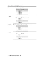
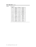
P1 Pinout
P1 and P2 provide a 3.3V power source.
Pin
Description
1
Ground (Black wire)
2
Ground (Black wire)
3
Ground (Black wire)
4
3.3V (Brown wire)
5
3.3V (Brown wire)
6
3.3V (Brown wire)
P2 Pinout
Pin
Description
1
Ground (Black wire)
2
Ground (Black wire)
3
Ground (Black wire)
4
3.3V (Brown wire)
5
3.3V (Brown wire)
6
3.3V (Brown wire)
P5 Pinout
P5 and P6 provide 5V power for additional drives.
Pin
Description
1
5V (Red wire)
2
5V (Red wire)
3
5V (Red wire)
4
Ground (Black wire)
5
Ground (Black wire)
6
Ground (Black wire)
P6 Pinout
Pin
Description
1
5V (Red wire)
2
5V (Red wire)
3
5V (Red wire)
4
Ground (Black wire)
5
Ground (Black wire)
6
Ground (Black wire)
Summary of Contents for Goliath
Page 1: ...Goliath PCI Quad Pentium Pro EISA System User s Guide MAN 730 6 7 96 ...
Page 45: ......
Page 71: ...Goliath PCI Pentium Pro EISA System User s Guide 66 ...
Page 77: ...Goliath PCI Pentium Pro EISA System User s Guide 72 ...
Page 78: ...Chapter 3 Programming the Flash ROM 73 A Mechanical Drawings ...
Page 79: ...Goliath PCI Pentium Pro EISA System User s Guide 74 ...

