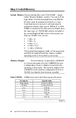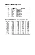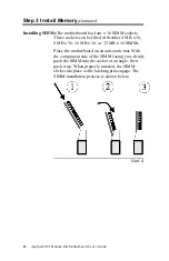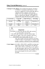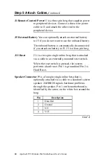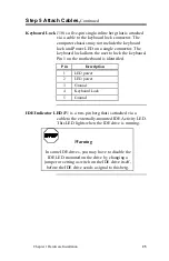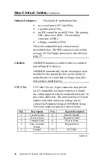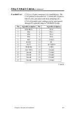
Chapter 1 Hardware Installation
23
Step 5 Attach Cables,
Continued
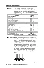
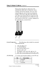
When connecting chassis connectors to the
motherboard, make sure to connect the correct
connector end. Most connector wires are color-
coded. Match the color of the wires leaving the
switch or LED to the same pin on the connector
end. There may be more than one connector with
the same color-coded wires. If so, follow the wire
to the switch or LED. Pin 1 is always indicated on
the motherboard, as shown below:
List of Connectors
The following cables should be connected
to the motherboard:
•
CPU fan cable to J7,
•
J5 External Battery,
•
Reset Switch cable to J11,
•
Speaker cable to J9,
•
Keyboard Lock Power LED cable to J10
•
IDE LED Activity Indicator LED cable to JP1.
J7 CPU Fan
J7 is a three-pin berg that attaches to the CPU fan.
Pin
Description
1
Ground
2
+12V
3
Ground
Cont’d


