Chapter 1 Hardware Installation
13
Step 3 Install Memory,
Continued
Configure Cache Memory
The motherboard supports 256 KB or
512 KB of L2 secondary cache memory. Cache
memory is supplied by American Megatrends in a
standard COAST-compliant cache memory
module. The cache module can support pipeline
burst or asynchronous SRAMs. The Apollo II is
shipped with empty SRAM and tag RAM sockets.
L2 Cache Size
Cache DIP
Type
Tag RAM Type
JS1 Setting
256 KB
32 x 8 KB
8 x 8 or
32 KB x 8
Short Pins 1-2
512 KB
64 KB x 8
32 KB x 8
Short Pins 2-3
0 KB
None
None
N/A
!
Important
The Apollo II works with either the DIP cache memory
or a cache module, but not both.
If the DIP cache memory is used, the cache module
socket must be empty. If the cache module is used, the
SRAM DIPs must be physically removed.
The cache module used must conform to the Intel
COAST Version 1.0 specification. A 160-pin cache
module connector is mounted on the motherboard.
Cache Jumpers
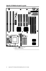
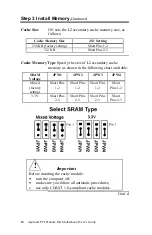
JS1, JPW1, JPW2, JPW3, and JPW4 are three-pin
bergs that select the external cache size and type.
JPW1, JPW2, JPW3, and JPW4 are to the right of
the SRAM module connector. JS1 is located to the
left of the SRAM connector. These jumpers do not
have to be changed when the cache module is
installed.
Cont’d

