


AD32 ENHANCED TOUCH TRACKER W/VMS
8000-2671-02, REV. A
INSTALLATION INSTRUCTIONS
3
4. Connect the power transformer cable and the
SensorNet data cable, and if required, the data
cable to EIM #2, to the compression connector,
and connect it to J3 on each EIM.
5. Wire the DB9 connector to the data cable. See
the tables in
Figure 1
. Assemble the hood onto
the DB9 connector.
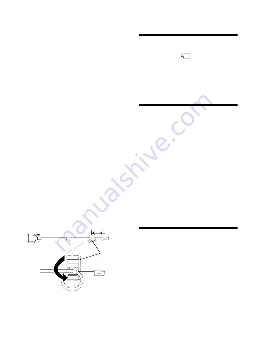
6. Install the ferrite core onto the cable assembly,
2.54-3.81cm (1 in.-1.5 in.) from the RJ45
connector (see
Figure 2
).
7. Connect the data cable to J1 on the EIM to the
RS232 port 1 (primary) or port 2 (secondary) on
the rear panel of the Video Matrix Switcher.
8. Connect a modular cable to J2 on EIM and to the
T
OUCH
T
RACKER
controller.
9. Plug each power transformer into a grounded,
3-wire receptacle.
NOTE:
If the keypad and backlighting do not
illuminate when power is applied, unplug the
power transformers, check all wiring connections,
and repeat step 9.
10. Press
Menu
to configure the T
OUCH
T
RACKER
controller as a primary or secondary unit.
11. Page down the screen to the
Tog Primary/2nd
menu option.
12. To select the
Tog Primary/2nd
menu option,
press the zoom (top line) or focus (bottom line)
button, as appropriate.
13. Press
Next
to toggle between using the T
OUCH
T
RACKER
controller as the primary unit or as the
secondary unit.
14.
Press
Menu
to reset the T
OUCH
T
RACKER
controller as a primary or secondary unit. The
controller will reboot to the Camera Control Mode.
Figure 2. Ferrite Core Attachment
0 in
2.54 - 3.81 cm
(1" - 1.5")
Resetting a Dome
1. Use the number buttons to select the dome to
reset, then press
(the
Camera
button).
2. Press
Menu
.
3. Using the Tracker Ball, scroll down to
Reset Dome.
4. Press
the
zoom (top line) or focus (bottom line)
button to select the
Reset Dome
menu option.
The T
OUCH
T
RACKER
will send a request to the selected
dome to reboot.
Switching Primary and
Secondary Functions
between Controller Units
1. Press
Menu
.
2. Using the Tracker Ball, scroll down to
Tog Primary/2nd.
3. Press
the
zoom (top line) or focus (bottom line)
button to select the
Tog Primary/2nd
menu
option.
An asterisk (*) identifies the current setting for
the T
OUCH
T
RACKER
.
4. Press
Next
to toggle between using the
primary unit for SensorNet polling and alarm
monitoring or as the secondary unit with
limited user functionality.
5. Press
Menu
to reset the controller as a
primary or secondary unit.
The controller will reboot and return to the Camera
Control Mode.
Adjusting V-Phase
1. Press
Menu
.
2. Using the Tracker Ball, scroll down to
Adjust V-phase.
3. Press
the
zoom (top line) or focus (bottom line)
button to select the
Adjust V-phase
menu
option.
4. Press
Next
or
Prev
to observe V-phase
through the oscilloscope or Fluke scope.
5. Press
Menu
to exit.
Off-line domes or fixed cameras will generate a warning
beep and disallow use of the V-phase utility. For
additional information on adjusting V-phase, see the
Service section of the View Manager 32 manual.
Ferrite
RJ45
DB9(M
)
Place 1 loop into
core slot; close core
halves; gently pull
cable to tighten loop.


