


80
Installation and Operation Guide
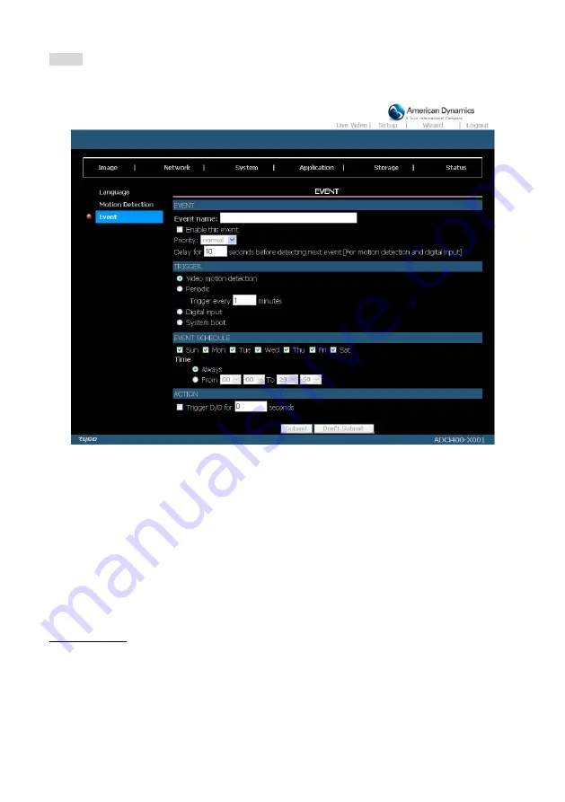
Event:
Click on the
Add
button in the Event column to enter the “Event” setting page.
Figure 5.37 Event
1.
Enter the Event name. Checkmark the “Enable this event” box and activate the function. Then
set the Priority and the Source from the drop-down list.
"Priority":
The event with higher priority will be executed first.
2.
Select the event trigger mode.
"Video motion detection":
Select the windows which need to be monitored.
"Periodic":
The event is triggered in specified intervals. The unit of trigger interval is a minute.
"Digital input":
The event is triggered when the DI status is changed by an external device.
"System boot":
The event is triggered when the system boots up.
3.
Set the recording schedule time.
4.
Set the Trigger D/O of activating the action. Check it to trigger digital output for specific
seconds when an event is triggered.
5.
Click on “Submit” to save or click on “Don’t Submit” to go back to the Event main page.
Event settings:
(1) Click Add under the Event column on Event Settings page to open the Event setting page. On
this page, you can arrange three parts
–Trigger, Event Schedule, and Action to set an event. A
total of 3 event settings can be configured.
(2) Enter the Event Name for the event setting.
(3)
Select “Enable this event” option to enable the event setting.
(4) Set th
e event priority from: “normal”, “high” and “highest”. Events with a higher priority will be
executed first.
(5) Enter the duration in seconds to pause motion detection after a motion is detected (for the
trigger types - motion detection and digital input
– use only).


