


INSTALLATION AND SERVICE GUIDE
DeltaDome II Camera Dome
8000-2708-01, REV. B
15
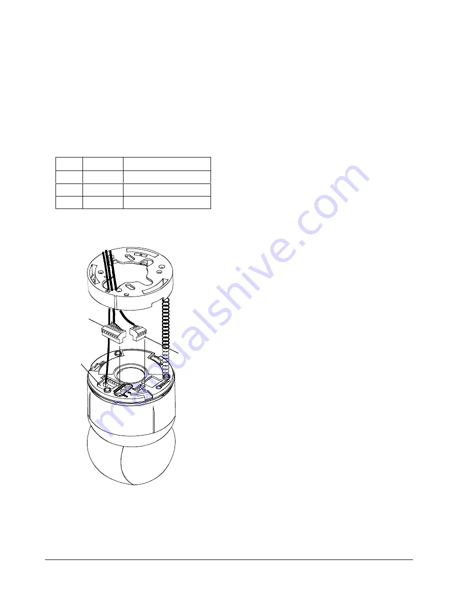
6. Connect 4-pin plug (alarm input/output) to 4-pin
receptacle (Figure 13).
a. Feed cable through access hole in base.
b. Connect alarm wires to 4-pin plug (refer to
chart below).
c. Insert plug into mating receptacle in top of
housing and eyeball assembly.
Alarm connections
Pin
Color
Designation
1
—
+12Vdc
2
—
Alarm Out
3
—
Alarm In
4
—
Common
Figure 13. Cable connections (Manchester
requires separate cables for data and power)
7. Check LEDs to verify that power and data are
reaching dome (Figure 13).
LEDs CR2, CR3, and CR4 surround video
connection and are visible through opening.
LEDs light in the following order:
To test Manchester network:
a. Yellow CR4 LED glows steadily indicating
communication between controller and
dome, or glows steadily, turns off, and then
blinks.
Note:
CR4 only blinks when both
Manchester wires are connected. Green
CR2 LED is not used to test Manchester.
b. Red CR3 LED blinks slowly indicating that
dome software is operating.
To test SensorNet or RS422 network:
a. Green CR2 LED blinks indicating data
present.
Yellow CR4 LED glows steadily indicating
communication between controller and dome
(RS422), or glows steadily, turns off, and
then blinks (SensorNet).
Note:
To check RS422 connections, set
dome address switch SW3 to 9 and check
red and green LEDs. Red should be off,
green should blink. If red blinks, RS422 is
wired backwards. If red and green are off,
then RS422 communication is absent. When
done with this test, set switch SW3 back to 0
and reset dome from controller.
b. Red CR3 LED blinks slowly indicating that
dome software is operating.
9-pin plug
LEDs CR2,
CR3, and CR4
visible through
opening.
4-pin plug


