24
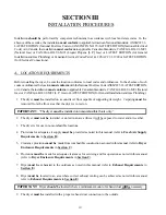
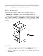
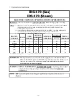
The “LINE POWER” and the “GROUND” connections to the dryer
must be
made through the knock out
hole at the top of the electric service/relay box. A strain relief
must be
used where the line power ground
wires go into the electric service/relay box.
Providing local codes permit, power connections to the dryer can be made by use of a flexible underwriters
laboratory list cord/pigtail (wire
must conform
to ratings of the dryer), or the dryer can be hard wired
directly to the service breaker. In
ALL
cases, a strain relief
must be
used where the wire(s) enter the
dryer electrical service (relay) box.
NOTE: A CIRCUIT SERVICING EACH DRYER
MUST BE
PROVIDED.
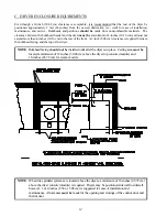
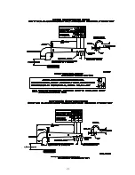
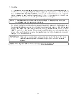
3. Electrical Connections
NOTE
: A wire diagram is included with each dryer and is affixed to the back side of the top control
(access) door.
The only electrical input connections to the dryer are the 3-phase (3ø) power leads (L1, L2, and L3),
GROUND, and in the case of 4 wire service, the NEUTRAL. These electrical connections are made at
the terminal block located in the service/relay box at the rear, upper left hand corner of the dryer. To gain
access into this service box, the service cover
must be
removed.
Summary of Contents for ID-170
Page 25: ...21 ...
Page 55: ...ADC 113331 1 08 27 01 25 ...

