


20. Step Up/Cross Setup Button:
This has two functions:
1. In manual chase or program modes, this button is used to
select the next step, (scene) in the pattern. The current step
will be displayed by the right two digits in the LCD display (6).
Holding down this button will quickly advance through the steps
(scenes). Tapping this button will increase the pattern by one.
2. When used with the SHIFT BUTTON (16) this button is used to
activate or disengage the CROSS FUNCTION.
21. Step Down/Blind Button:
This has two functions:
1. In manual chase or program modes this button is used to
select the previous step (scene) in the pattern. The current step
will be displayed by the right two digits in the LCD display (6).
Holding down this button will quickly scroll backward through the
selected chase steps (scenes). Tapping this button will decrease
the pattern by one.
2. When used with the SHIFT BUTTON (16) during CHASE MODE,
this button will engage or disengage the BLIND FUNCTION.
22. Loop/Loop Exit Button:
This button serves two functions:
1. This button is used to activate and set chase programs into
LOOP MODE.
2. Used with the SHIFT BUTTON (16), this operation will disengage
and clear LOOP MODE.
23. Program/End Step Button:
This button has three functions:
1. This button is used to engage PROGRAM MODE.
2. When in PROGRAM MODE, this button is used to load a scene
into a chase pattern.
3. When used with the SHIFT BUTTON (16), this button is used to
finalize a program.
24. Chase/Audio Button:
This button has two (2) functions:
1. This button is used to enter CHASE MODE.
2. Used with the SHIFT BUTTON (16), this button will activate
AUDIO MODE.
25. Assign/Delete Program Button:
This button serves two functions:
1. This button activates the ASSIGN function. This functions allows
you to ASSIGN a group of channels to a single FLASH BUTTON
(1 & 13).
2. In PROGRAM MODE, this button, when used with the SHIFT
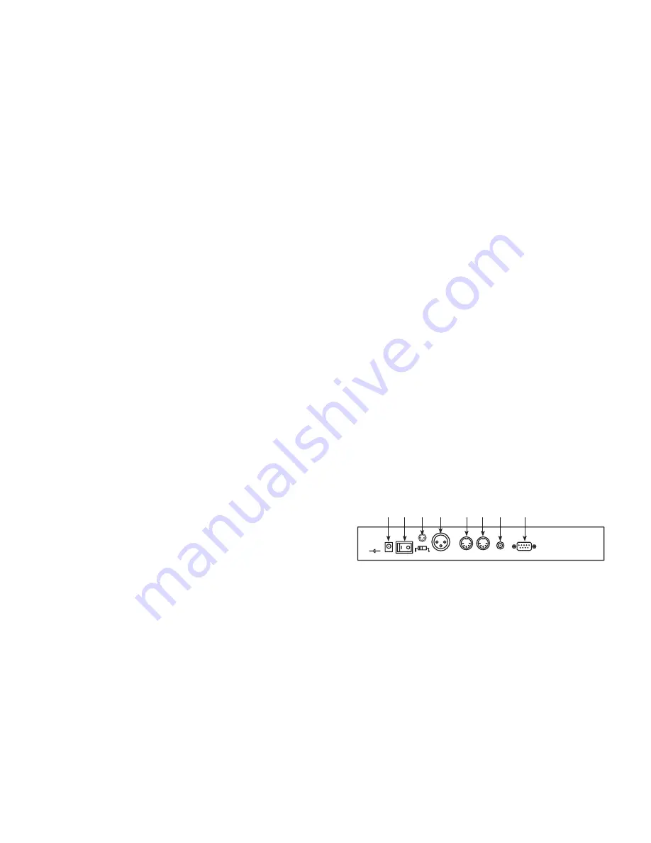
POWER
DMX OUT
MIDI THRU
MIDI IN
FOOT CONTROL
LINE INPUT
100 mV-1Vpp
DC INPUT
DC 12V-20V,
250mA min.
+
-
Polarity Select
1-Ground
2-Data-
3-Data+
1-Ground
2-Data-
3-Data+
3 1
3 7
3 6
3 5
3 4
3 3
3 2
3 0
Function and Controls - Rear Panel
BUTTON (16), is used to delete a program (CHASE) pattern.
26. Tap Sync/Manual Step Button:
This button has two functions:
1. In CHASE MODE, this button is used to set a momentary speed.
Channels 1-8 will then chase to this beat.
2. When used with the SHIFT BUTTON (16), this button is used to
activate the MANUAL STEP MODE. This mode allows you to
manually select chases and control steps for channels 1-8.
27. Patch/Midi Channel Button:
This button is used to activate the
PATCH FUNCTION or to set the MIDI channel:
1. To activate the PATCH function, hold down this button for two
seconds. The red PATCH LED will glow indicating PATCH is
ready to be set or changed.
2. To activate the MIDI channel adjustment settings, press and hold
down the PATCH/MIDI CHANNEL BUTTON for two seconds
while holding down the SHIFT BUTTON (16).
28. Stand By/Manual Button:
This button is used to select Stand By
and Manual functions:
1. When the unit is powered on, it will always default to Stand By
mode (no output). Pressing this button will take you in and out
of Stand By mode.
2. Hold down the SHIFT BUTTON (16) while pressing this button to
enter MANUAL OPERATION MODE.
29. Full On Button:
Pressing this button will bring FADER CHANNELS
1-8 (3) to full output.
30. Power Input:
Connect the included external power supply to this
connection. Be sure to only a recommened power supply DC 12v-
20v, 250mA min.
31. Power Switch:
This switch connects and disconnects main power.
32. DMX Polarity Switch:
This switch changes the DMX line polarity to
©American DJ Suply® www-americandj.com Light Stantion Instruction Manual Page 7
©American DJ Suply® www-americandj.com Light Stantion Instruction Manual Page 8


