American DJ
®
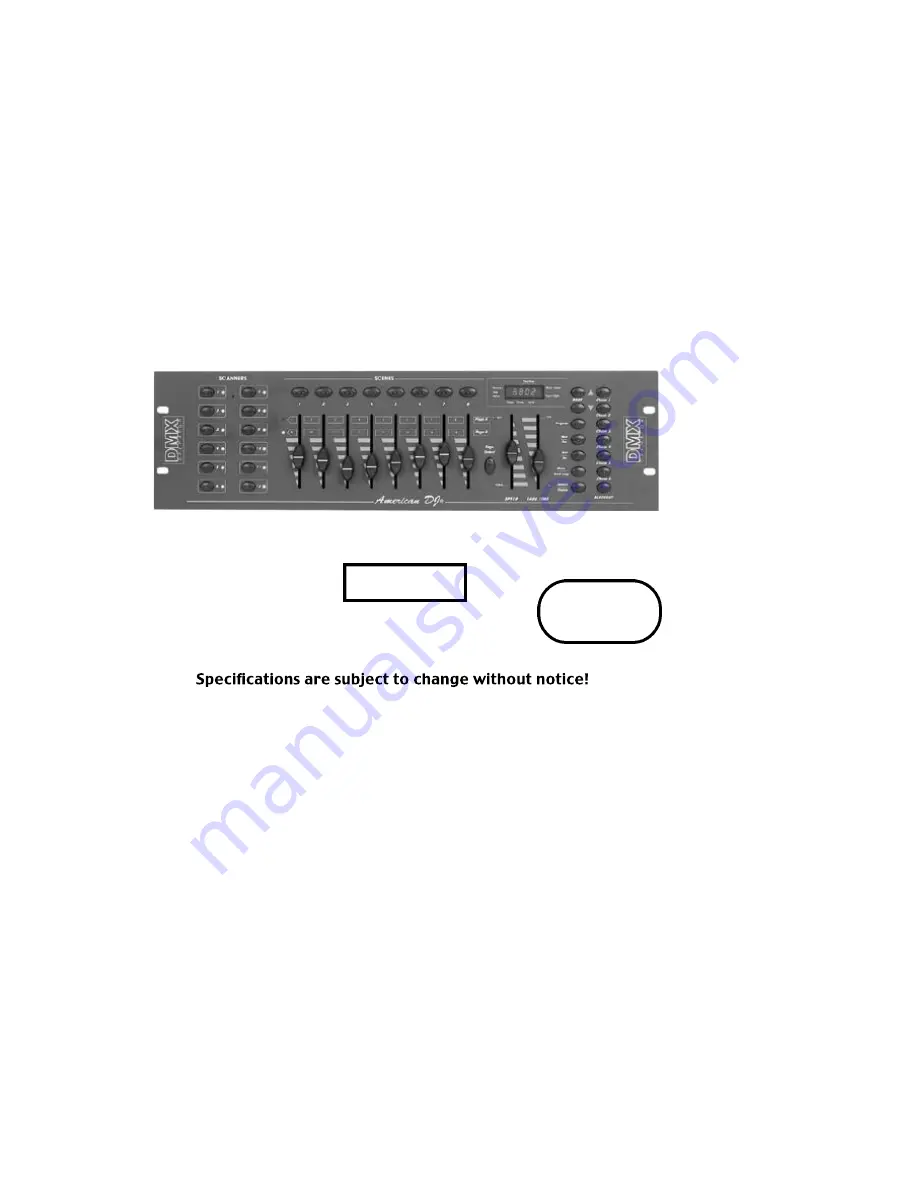
DMX OPERATOR
™
User Instructions
DMX-512
MIDI
C A PA B L E
American DJ Los Angeles, CA 90058 -
2000
Page 1: ...American DJ DMX OPERATOR User Instructions DMX 512 MIDI CAPABLE American DJ Los Angeles CA 90058 DMX OPERATOR 2000...
Page 2: ...BANK OF SCENES 13 RESET ALL SCENES 13 PROGRAMMING CHASES 14 EDITING CHASES 14 INSERT A STEP 14 DELETE A STEP 15 DELETE A COMPLETE CHASE 15 DELETE ALL CHASES 15 PLAYBACK SCENES CHASES 16 MANUAL RUN SC...
Page 3: ...Operator ADDRESS FIXTURES pg 4 to 7 PROGRAM SCENES up to 240 pg 8 9 PROGRAM CHASES up to 6 of 240 scenes pg 12 PLAYBACK CHASES up to 240 pg 14 PLAYBACK SCENES 8 AT A TIME 30 BANKS OF 8 pg 14 American...
Page 4: ...more information 2 SCENE BUTTONS Used to store Scenes in program mode or playback your scenes in playback mode 3 LCD DISPLAY Displays values and settings depending on the chosen function 4 BANK BUTTON...
Page 5: ...X Operator 30 seconds to complete the change from one scene to the next 13 SPEED SLIDER Used to adjust the rate of chase speed in Auto Mode 14 PAGE SELECT Used to select faders between PAGE A 1 8 and...
Page 6: ...0 to 255 You set the address for each receiver fixture by using Dip switches or some type of digital readout While DMX 512 is the standard used to control lighting at this time there are some differen...
Page 7: ...etting ADDRESS for Setting ADDRESS for 17 unit starts at 49 unit starts at CHANNEL 17 CHANNEL 49 Dip switch 1 1 Dip switch 1 1 5 16 5 16 17 6 32 49 DIP SWITCH DMX ADDRESS 1 2 3 5 4 7 9 10 8 6 ON 1 4 1...
Page 8: ...s at CHANNEL 1 all Dip switches OFF Setting ADDRESS for Setting ADDRESS for 17 49 Dip switch 5 16 Dip switch 5 16 16 6 32 48 unit starts at 17 unit starts at 49 DIP SWITCH DMX ADDRESS 1 2 3 5 4 7 9 10...
Page 9: ...on 2 starts at 17 Scanner Button 3 starts at 33 Scanner Button 4 starts at 49 Scanner Button 5 starts at 65 Scanner Button 6 starts at 81 Scanner Button 7 starts at 97 Scanner Button 8 starts at 113 S...
Page 10: ...e adjusting this stops adjustment of that Fixture s You then press another SCANNER BUTTON to select another Fixture to adjust You can adjust more than one fixture at a time by selecting more than one...
Page 11: ...IMES 12 Adjust the Pan fader to adjust the mirrors to go across to the other top corner of the dance floor By pressing Scene buttons 1 to 4 in order you should have a box pattern If you have a problem...
Page 12: ...his function allows you to make changes in a scene after it has been programmed 1 Press the PROGRAM BUTTON FIG 6 for three 3 seconds to activate program mode The LCD DISPLAY FIG 3 will indicate progra...
Page 13: ...While holding down the AUTO DEL BUTTON FIG 8 press and hold the MUSIC BANK COPY BUTTON FIG 9 at the same time 4 Release both buttons at the same time the LCD DISPLAY FIG 3 should flash momentarily to...
Page 14: ...ous fast blinking dot next to Blackout You May now playback the Chase Recorded Pg 14 EDITING CHASES INSERT A STEP 1 Press the PROGRAM BUTTON FIG 6 for three 3 seconds to activate program mode The LCD...
Page 15: ...wish to delete press and release the AUTO DEL FIG 8 DELETE A COMPLETE CHASE 1 Press and hold down the CHASE BUTTON FIG 5 that you want to delete 2 While holding down the CHASE BUTTON FIG 5 press and r...
Page 16: ...TAP SYNC BUTTON FIG 11 6 Use the BANK BUTTONS FIG 4 to scroll through the chase Note Display will show the number of the step in the Chase not the Scene bank or number AUTO RUN SCENES This function wi...
Page 17: ...tting or your scenes will not be completed before a new step is sent Note If you want to include all the Chases PRESS AUTO DEL BUTTON before selecting Chase MUSIC RUN SCENES 1 Press the MUSIC BANK COP...
Page 18: ...8 TO 15 1 to 8 of Bank 1 on or off BANK 3 16 TO 23 1 to 8 of Bank 1 on or off BANK 4 24 TO 31 1 to 8 of Bank 1 on or off BANK 5 32 TO 39 1 to 8 of Bank 1 on or off BANK 6 40 TO 47 1 to 8 of Bank 6 on...
Page 19: ...s Audio Chase Speed and Fade time adjustments CABLE TERMINATION When total run of Control cable is 90 or over it is necessary to terminate the Cable This can be accomplished as follows 1 Many Fixtures...
Page 20: ...UTTON LED s should blink after pressing each SCENE BUTTON Make sure you are in the correct Bank that has scenes recorded Scenes don t playback correctly like I recorded them Was Scanner for all fixtur...
Page 21: ...1 2 3 5 4 7 9 10 8 6 ON 1 2 3 5 4 7 9 10 8 6 ON 1 2 3 5 4 7 9 10 8 6 ON 1 2 3 5 4 7 9 10 8 6 ON 1 2 3 5 4 7 9 10 8 6 ON Scanner 1 Channel 1 Scanner 2 Channel 17 Scanner 3 Channel 33 Scanner 4 Channel...
Page 22: ...7 9 10 8 6 ON 1 2 3 5 4 7 9 10 8 6 ON 1 2 3 5 4 7 9 10 8 6 ON 1 2 3 5 4 7 9 10 8 6 ON 1 2 3 5 4 7 9 10 8 6 ON 1 2 3 5 4 7 9 10 8 6 ON Scanner 1 Channel 1 Scanner 2 Channel 17 Scanner 3 Channel 33 Scan...