This manual MUST be given to the user of the product.BEFORE using this product, read this manual and save for future reference.
User Manual
Electric Portable Patient Lift
Page 1: ...This manual MUST be given to the user of the product BEFORE using this product read this manual and save for future reference User Manual Electric Portable Patient Lift...
Page 2: ...SEMBLY 15 Introduction 15 Unpacking the Patient Lift 15 Assembling the Mast to the Base 16 Assembling the Boom Actuator 17 Installing the Leg Actuator to the Base 18 Mounting the Battery Charger 19 6...
Page 3: ...Cleaning the Sling and the Lift 36 Replacing the Boom Actuator 36 Checking and Tightening Mast Pivot Bolt 37 Replacing the Swivel Bar 38 Maintaining the Base Adjustment 39 Replacing Casters Forks 40 R...
Page 4: ...dous situation which if not avoided will result in death or serious injury WARNING Warning indicates a potentially hazardous situation which if not avoided could result in death or serious injury CAUT...
Page 5: ...used please prepay shipping charges LIMITATIONS AND EXCLUSIONS THE FOREGOING WARRANTY SHALL NOT APPLY TO SERIAL NUMBERED PRODUCTS IF THE SERIAL NUMBER HAS BEEN REMOVED OR DEFACED PRODUCTS SUBJECTED TO...
Page 6: ...ended for use with Invacare products NOTICE THE INFORMATION CONTAINED IN THIS DOCUMENT IS SUBJECT TO CHANGE WITHOUT NOTICE WARNING The Invacare patient lift is NOT a transport device It is intended to...
Page 7: ...ommends that two assistants be used for all lifting preparation transferring from and transferring to procedures our equipment will permit proper operation by one assistant The use of one assistant is...
Page 8: ...es of the sling equally Make sure that there is sufficient head support when lifting a patient WARNING When using an adjustable base lift the legs MUST be in the maximum Opened Locked position before...
Page 9: ...oot must be tight to ensure safe use of the patient lift Bolt must be checked at least every six months in conjunction with periodic maintenance WARNING Maintenance MUST be performed ONLY by qualified...
Page 10: ...s Carefully read battery battery charger information prior to installing servicing or operating your patient lift WARNING This product has been supplied from an environmentally aware manufacturer that...
Page 11: ...roll casterbase over uneven surfaces that may cause the Patient Lift to tip over DO NOT lock the casters of the Patient Lift when lifting an individual Casters MUST be left unlocked to allow Patient...
Page 12: ...ght Clearance 4 5 inches Base Length 48 0 inches Caster Size FRONT REAR 3 0 5 0 inches Sling Options 3 Styles 1 Style Weight Capacity 450 lbs 600 lbs Weight IN Carton 136 lbs 141 lbs Weight OUT of Car...
Page 13: ...A N A 7 Length 54 7 60 5 65 3 54 7 60 5 65 3 59 8 62 8 67 8 72 3 37 55 55 Commode Opening N A N A N A 11 11 13 N A N A N A N A N A N A 13 Back N A N A N A N A N A N A 29 2 35 7 41 7 43 2 N A N A N A W...
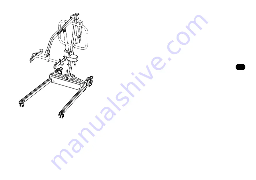
Page 14: ...rts in the assembly of this patient lift The base legs mast boom assembly and the swivel bar are manufactured to specifications that assure correct alignment of all parts for safe functional operation...
Page 15: ...ast in an upright position and place the mast into the U shaped cut out of the base 4 Insert shoulder bolt with washers through the base and mast 5 Secure with nut WARNING The mast may be removed from...
Page 16: ...over the shaft extension of the boom actuator 7 Align the holes of the boom assembly mounting bracket with those of the boom actuator and insert the bolt Secure with nut CAUTION DO NOT overtighten the...
Page 17: ...actuator to the mast bracket A Position leg actuator between mast brackets B Move the legs to align the holes in the leg actuator with the holes in the mast bracket C Install the pin through the hole...
Page 18: ...1 8 inch gap between the screw head and the wall 5 Install the battery charger with mounting bracket onto the bottom mounting screw 6 Drill the remaining two mounting holes 7 Install the two remaining...
Page 19: ...eral times with proper supervision and a capable individual acting as a patient The legs of the lift must be in the maximum open position for optimum stability and safety If it is necessary to close t...
Page 20: ...only retract while under load and the mechanical Emergency release is pulled The release is colored reddish orange with the word Emergency spelled out in white Secondary Emergency Release In cases wh...
Page 21: ...s the RED ORANGE emergency button on the control box in to stop the boom assembly and patient from raising or lowering Rotate the RED ORANGE emergency stop button clockwise to disengage the emergency...
Page 22: ...olong battery life An audible alarm will sound horn will beep when battery is low CAUTION Make sure there is an audible click when mounting battery on the battery charger to confirm proper mounting Ot...
Page 23: ...nt is based on the evaluation of the health care professional for each individual case Refer to Safety on page 7 in this manual before proceeding further and observe all warnings indicated Before posi...
Page 24: ...l Nos R110 R117 Full Body Slings and Model No R121 Toileting Sling have four sling straps Model Nos R100 R102 Divided Leg Slings have six sling straps Invacare Lift Swivel Bars have three hookup point...
Page 25: ...uld cause the patient lift to tip and endanger the patient and assistants DO NOT move the patient if the sling is not properly connected to the hooks of the swivel bar When the sling is elevated a few...
Page 26: ...LIFTING THE PATIENT 27 Electric Portable Patient Lift FIGURE 7 1 Lifting Moving the Patient DETAIL A LIFTING THE PATIENT DETAIL B MOVING THE PATIENT DETAIL C MOVING THE PATIENT LIFT AWAY FROM THE BED...
Page 27: ...jury or damage may occur DO NOT lock the rear casters of the patient lift when lifting an individual Locking the rear casters could cause the patient lift to tip and endanger the patient and assistant...
Page 28: ...ess the boom down button to lower the patient onto the commode chair leaving the sling attached to the swivel bar hooks 5 When complete recheck the sling for correct attachments 6 Press the boom up bu...
Page 29: ...nt in a wheelchair refer to Transferring to a Wheelchair on page 31 8 4 Transferring to a Bathing Unit 1 Lift the patient from the bed Refer to Lifting the Patient on page 24 2 Press the boom up down...
Page 30: ...to lower the patient either by opening the control valve or by pressing the boom down button 8 Two assistants are recommended for this step One assistant stands behind the chair and the other operate...
Page 31: ...on page 23 Rotate RED emergency stop button CLOCKWISE until it pops out Reconnect the battery to the control box Refer to Charging the Battery on page 23 Replace the battery pack Refer to Charging the...
Page 32: ...ed in this manual to keep your patient lift in continuous service ITEM INITIALLY INSTITUTIONAL INSPECT ADJUST MONTHLY IN HOME INSPECT EVERY SIX 6 MONTHS THE CASTER BASE Inspect for missing hardware Ba...
Page 33: ...ck the bolt hooks for wear or damage Check sling hooks for wear or deflection Inspect pivot joints for wear X X X X X X X X X ACTUATOR ASSEMBLY Inspect hardware on mast boom and base Check for wear or...
Page 34: ...of any part of the lift contact your Dealer immediately and advise them of the problem 10 2 Lubricating the Lift The Invacare lift is designed for minimum maintenance However a six month check and lub...
Page 35: ...F 82 C and a biocidal anti biological solution A soft cloth dampened with water and a small amount of mild detergent is all that is needed to clean the patient lift The lift can be cleaned with non ab...
Page 36: ...slide it off the mast along the boom 2 Check that the bolt is through the bracket and the locknut is tight and secure 3 If needed do one or more of the following Tighten locknut and back off the lock...
Page 37: ...el bar and mounting brackets of the boom should be inspected every six months to determine the extent of wear If these parts become worn replacement must be made Washers should be placed against both...
Page 38: ...se adjustment should not require any attention other than 1 Check that the legs are square when in the closed position 2 Place a square on the inside of the legs and base to determine the 90 alignment...
Page 39: ...unting holes in the new rear caster and the fork 5 Install the bolt through the fork and new rear caster and tighten securely with the locknut WARNING Ensure that there is sufficient room to turn pati...
Page 40: ...aster assembly and tighten securely with the locknut Replacing Forks 1 Place the lift on its side 2 Remove the front or rear caster from the lift Refer to Replacing Casters Forks on page 40 3 Unscrew...
Page 41: ...e unable to understand the Warnings Cautions or Instructions contact a healthcare professional dealer or technical personnel before attempting to install this equipment otherwise injury or damage may...
Page 42: ...E 11 1 Removing the Swivel Bar Boom 600 lift swivel bar not shown Locknut Save for installing Scale Boom Mounting Bracket Pinch Guard 450 lb Swivel Bar Shoulder Bolt Save for installing scale Swivel B...
Page 43: ...with the mounting holes in the load cell assembly Refer to Detail B in FIGURE 11 2 5 Secure swivel bar pin to the load cell assembly with the provided mounting screw and locknut Securely tighten Refe...
Page 44: ...ft FIGURE 11 2 Installing the Reliant Scale Locknut Swivel Bar Nylon Washers Swivel Bar Pin Mounting Screw Boom Reliant Scale Boom Mounting Bracket Reliant Scale Nylon Washer Load Cell Assembly Should...
Page 45: ...indow The function of this key is to change the unit of measurement from pounds lb to kilograms kg LOCK UNLOCK LOCK Lower Right Corner of the Display Window This key is used to lock or unlock a weight...
Page 46: ...d by the word LOCK appearing in the display window WARNING The weight capacity is limited to the lowest rated capacity of any one of the components in use e g Patient Lift Sling or Scale The patient s...
Page 47: ...pound For example a patient weighing one hundred pounds the scale will fluctuate between 99 8 and 100 2 until the LOCK key is pressed Fluctuation of the weight displayed is normal as noted above Pres...
Page 48: ...display window 7 Perform one of the following A FOR CAL1 OPTION support 50 pounds of calibrated weight from the scale and press the ZERO key B FOR CAL2 OPTION support 200 pounds of calibrated weight...
Page 49: ...Battery failure Check battery Replace if necessary Battery has been replaced and unit still does NOT work properly Contact Invacare for Service at 1 800 333 6900 CALIBRATION REQUIRED Indicates imprope...