20 Gear Drive, Plymouth Ind. Park, Terryville, CT 06786
Tel: (860) 585-1254 Fax: (860) 584-1973 http://www.amci.com
SD4840EK User Manual
I
NTRODUCTION
TO
THE
SD4840EK
17
Available Discrete Inputs (continued)
Stop Jog or Registration Move Input
When an input is configured as a Stop Jog or Registration Move Input, triggering this input during a Jog
Move or Registration Move will bring the move to a controlled stop. The controlled stop is triggered on an
inactive-to-active state change on the input. Only Jog Moves and Registration Moves can be stopped this
way, all other moves ignore this input.
If the quadrature encoder is enabled, the quadrature encoder position data will be captured when the DC input
makes an inactive-to-active transition if it is configured as a Stop Jog or Registration Move Input. The
encoder position data is not captured if a Jog or Registration Move is not in progress. If you want to capture
encoder position data on every transition of a DC input, configure it as a Start Indexer Move Input.
Capture Encoder Position Input
As described in the
and
Stop Jog or Registration Move Input
sections above, the
SD4840EK can be configured to capture the encoder position value on a transition of a discrete DC input.
General Purpose Input
If your application does not require all three inputs, you can configure the unused inputs as General Purpose
Inputs. The inputs are not used by the SD4840EK, but the input state is reported in the network data.
Available Discrete Output
The SD4840EK has a single DC output that has a maximum rating of 30 Vdc at 20 mA. The output can be
configured to be a general purpose output or a Fault Output. When configured as a Fault Output, the output
will conduct under normal conditions and will switch off when a fault occurs. The following faults affect the
Fault Output:
Reset ............... The driver initialization is not yet complete on power up.
Short Circuit ... Motor Phase to Phase or Phase to Earth Ground
Over Temp ..... Heat Sink temperature exceeds 90° C (195° F)
Faults are reported in the Network Input Data and can be cleared through the Network Output Data.
Ethernet Ports
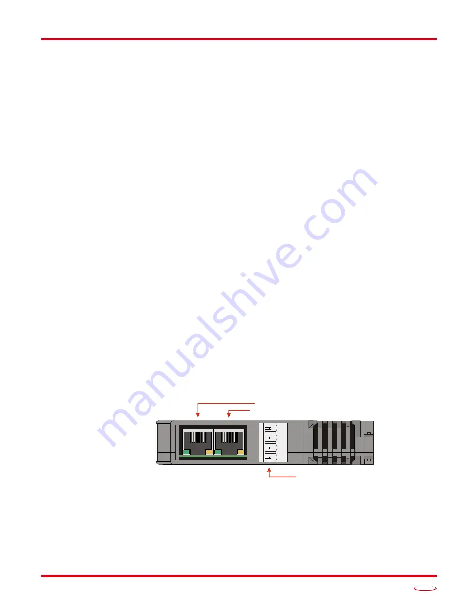
The Ethernet Interface on the SD4840EK driver has two standard RJ-45 jacks that accept any standard
100Base-TX cable. Both ports are also auto MDI-X capable. This means that a standard cable can be used
when connecting the Ethernet Driver to any device. Crossover cables are never needed.
Figure R1.2 Location of Ethernet Ports and Motor Connector
The “IN” network jack in the diagram above must be attached to the upstream device in the EtherCAT net-
work. (Closer to the network master.) The “OUT” jack must be attached to the next (downstream) device in
the network of the Networked Driver is not the last device in the network.
There are two LED’s on each of the RJ-45 jacks. The amber LED is not used. The green LED shows the link
status of the Ethernet connection. They are on when there is a physical connection between the SD4840EK
and the previous or next device in the network. They blink when data is being transmitted over the network.
Stepper Motor Connector
IN Ethernet Port
OUT Ethernet Port
SD4840EK Bottom View
B–
A–
B+
A+
Summary of Contents for SD4840EK
Page 1: ...MICRO CONTROLS INC ADVANCED U s e r M anual Manual 940 0S310...
Page 6: ...TABLE OF CONTENTS SD4840EK User Manual ADVANCED MICRO CONTROLS INC 6 Notes...
Page 38: ...MOVE PROFILES SD4840EK User Manual ADVANCED MICRO CONTROLS INC 38 Notes...
Page 48: ...CALCULATING MOVE PROFILES SD4840EK User Manual ADVANCED MICRO CONTROLS INC 48 Notes...
Page 78: ...COMMAND DATA FORMAT SD4840EK User Manual ADVANCED MICRO CONTROLS INC 78 Notes...
Page 94: ...INSTALLING THE SD4840EK SD4840EK User Manual ADVANCED MICRO CONTROLS INC 94 Notes...
Page 104: ...LEADERS IN ADVANCED CONTROL PRODUCTS ADVANCED MICRO CONTROLS INC...


