20 Gear Drive, Plymouth Industrial Park, Terryville, CT 06786 page: 23
Tel: (860) 585-1254 Fax: (860) 584-1973 Web: www.amci.com
ControlLogix 7252 LDT Interface Manual
Revision 1.5
Interpolation Command Programming Cycle
1.
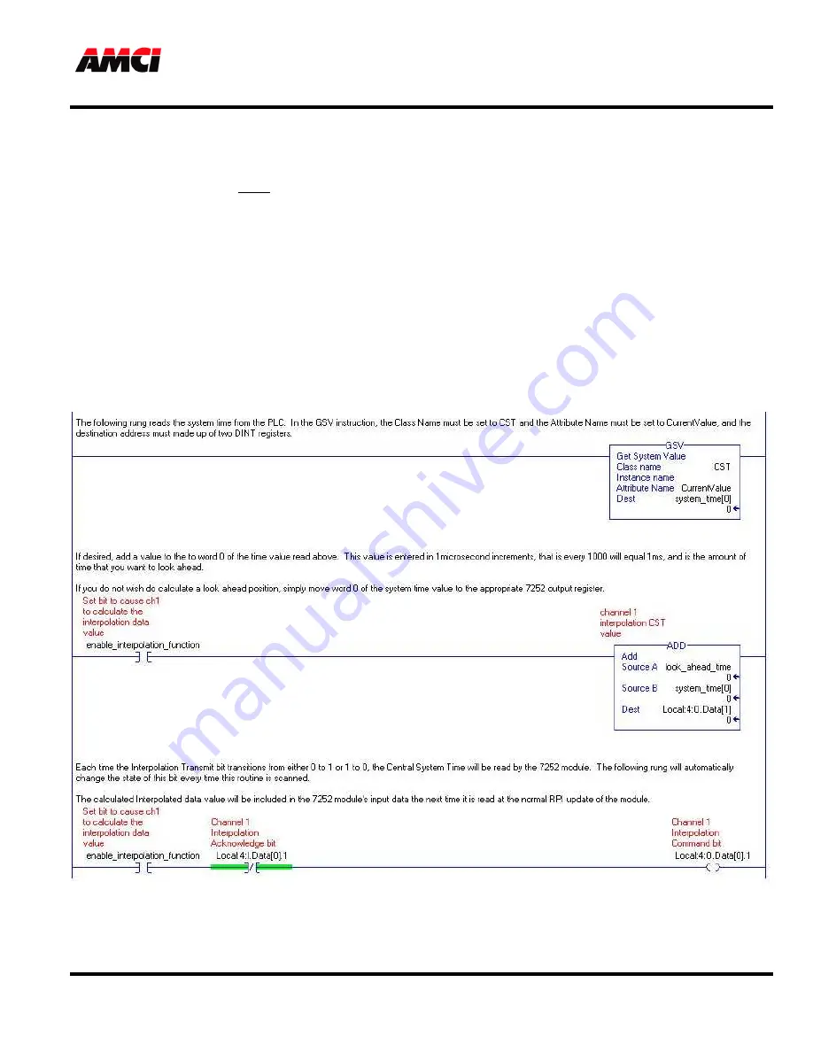
The ladder logic program reads the desired Central System Time value from the PLC using a GSV instruction.
The Destination tag must consist of at least two DINT registers.
2.
If desired, add the amount of time, in microseconds, that you want to “look ahead” to the lower word of
Central System Time.
3.
Write the desired Central System Time value into the Interpolation CST Value Output Register.
4.
Based on the state of the Interpolation Acknowledge bit, toggle the Interpolation Command bit either on or off.
5.
Based on the measured Velocity for the corresponding sensor channel, the 7252 module calculates the
Interpolated Data Value and places it in the respective Input Register. The 7252 module then adjusts the
Interpolation Acknowledge Bit accordingly.
If desired, the user can send the Interpolated Position, along with the system time, to another
ControlLogix module each time the Interpolation Acknowledged bit changes state.
The following is an example of the ladder logic that can be used to generate the Interpolation Data Value.


