www.amcelettronica.com
Installation Instructions
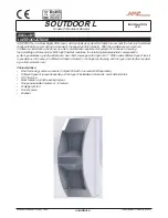
soutdoor L
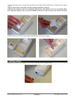
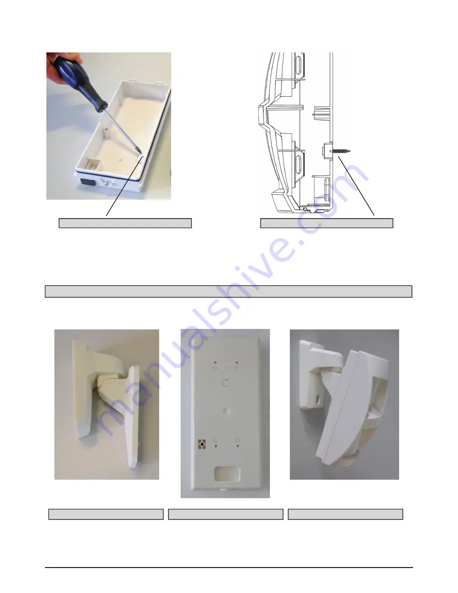
Remove the board, making a hole in the back of the upper cover for the cable to pass through in a suitable installation
position. Make another 2 holes to attach the sensor to the wall. We recommend using anchors that are no smaller
than 3 mm.
Once the cable and wall attachment holes have been made, take the measurement to attach an anchor (3 mm) to the
anti-removal system. (see above fig.1 and fig.2)
Then attach the bottom and re-close, taking into account the positioning mentioned previously.
Note: remember that the distance between the board and the base is 13.5 mm. Space reserved for the proper
positioning of the cable feeder or any piping to be inserted.
Screw for Anti-removal system - Fig.2
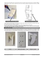
Using the bracket
You can use the bracket included in the package for attaching it to the wall. The back of the cover is ready for attach-
ment of the bracket and for the passage of the cables inside it. You can see how it should be used in the figure. In case
of use of the bracket, for the closure of the anti-removal tamper mount the specific screw, in the seat shown in Fig.1.
bracket
Screw for Anti-removal system - Fig.1
A B
C D
Bottom of the detector
De bracket

