Amazone Cenius 3003 Operating Manual Download Page 32


Product description 


4.6 

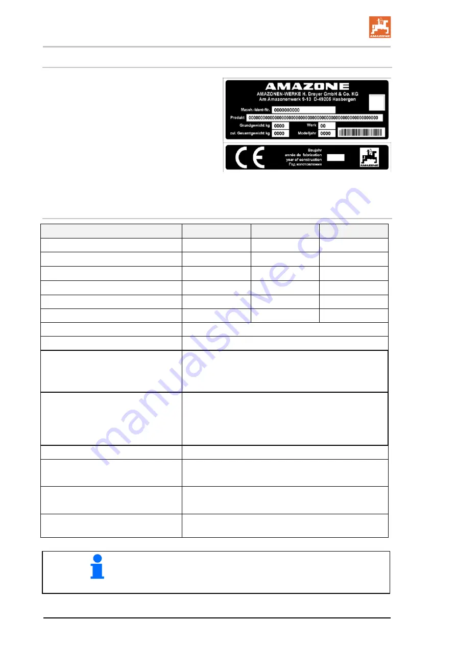
Rating plate and CE marking 

The rating plate specifies: 


Implement ID No. 


Product 


Basic weight kg  


Permissible total weight kg 


Factory 


Model year 


Model year 


4.7 

Technical data 

Cenius 

3003 

3503 

4003 

Working width 

3000 mm 

3500 mm 

4000 mm 

Transport width 

3000 mm 

3500 mm 

4000 mm 

with 

Double-disc coulter


3050 mm 

3550 mm 

4050 mm 

Wing coulter


3080 mm 

3580 mm 

4080 mm 

Tine spacing 

273 mm 

292 mm 

308 mm 

Number of tines 

11 

12 

13 

Number of tine rows 

Maximum working depth 

300 mm  

Overload protection of the tines: 


Cenius Super 

tension spring 

Cenius Special 

shear bolt 

Levelling unit: 


Concave discs 


Disc diameter 

460 


Alternative spring tines 


Working speed 

10-15 

Total length 

3,80  

4,25 (with tandem roller) 

Attachment category  

Category 2 or 3 

Diameter ofbolt: Category 3 

Centre of gravity distance (d) 

1900 mm 


You can find the value for the permissible total weight on the 
implement rating plate. 


Weigh the empty implement to determine the basic weight. 


32 


Cenius 03  BAG0144.5  10.19


Summary of Contents for Cenius 3003

Page 1: ...cultivator Cenius 3003 Cenius 3503 Cenius 4003 Special Super MG5552 BAG0144 5 10 19 Printed in Germany Read and observe this operating manual before using the machine for the first time Keep it in a s...

Page 2: ...only harm himself but also make the mistake of blaming the machine for the reason of a possible failure instead of himself In order to ensure a good success one should go into the mind of a thing or m...

Page 3: ...Postfach 51 D 49202 Phone E mail Hasbergen 49 0 5405 50 1 0 amazone amazone de Spare part orders Spare parts lists are freely accessible in the spare parts portal at www amazone de Please send orders...

Page 4: ...fore putting the machine into operation Only after careful reading will you be able to benefit from the full scope of your newly purchased machine Please ensure that all the machine operators have rea...

Page 5: ...of not observing safety instructions 20 2 15 Safety conscious working 20 2 16 Safety information for users 21 2 16 1 General safety and accident prevention information 21 2 16 2 Hydraulic system 24 2...

Page 6: ...8 3 Adjusting the stripper 63 9 Transportation 64 10 Use of the machine 65 10 1 Changing from transport to working position 65 10 2 Operation 65 10 3 Headland 65 11 Faults 66 12 Cleaning maintenance a...

Page 7: ...always viewed in the direction of travel 1 3 Diagrams used Instructions for action and reactions Tasks to be carried out by the user are presented as numbered in structions Always keep to the order of...

Page 8: ...tate To replace damaged warning pictograms Obligations of the user Before starting work anyone charged with working with on the ma chine is obliged To comply with the basic workplace safety instructio...

Page 9: ...erator at the latest on the comple tion of the contract Guarantee and liability claims for damage to peo ple or goods will be excluded if they can be traced back to one or more of the following causes...

Page 10: ...ical injury WARNING Indicates a medium risk which could result in death or serious physical injury if not avoided If the instructions are not followed then this may result in death or serious physical...

Page 11: ...ion equipment Before each commissioning of the machine all the safety and protec tion equipment must be properly attached and fully functional Check all the safety and protection equipment regularly F...

Page 12: ...in their assigned tasks and in the possible risks in the case of improper behaviour have been trained if necessary and have been in formed about the necessary protective equipment and measures 3 Peop...

Page 13: ...bolted connections are firmly secured and tight en if necessary When the maintenance work is completed check the function of the safety devices 2 10 Constructive changes You may make no changes expan...

Page 14: ...ties there is no guarantee that they have been designed and manufactured in such a way as to meet the requirements placed on them AMAZONEN WERKE accepts no liability for damage arising from the use of...

Page 15: ...r labels The following diagrams show the arrangement of the warning picto grams on the machine Always keep all the warning pictograms of the machine clean and in a legible state Replace illegible warn...

Page 16: ...e danger Warning pictograms explanation The column Order number and explanation provides an explanation of the neighbouring warning pictogram The description of the warning pictograms is always the sa...

Page 17: ...injuries Keep a sufficient safety distance from the machine as long as the tractor engine is running Ensure that all other persons also keep a sufficient safety distance from the danger area of the m...

Page 18: ...act a doctor immediately MD097 Risk of crushing and contusions between the rear of the tractor and the machine when coupling and uncoupling the machine These dangers can cause extremely serious and po...

Page 19: ...operating manual MD114 This pictogram indicates a lubrication point MD199 The maximum operating pressure of the hydrau lic system is 210 bar MD225 Risk of crushing of the entire body due to standing...

Page 20: ...ure of important machine functions Failure of prescribed methods of maintenance and repair Danger to people through mechanical and chemical impacts Risk to environment through leakage of hydraulic flu...

Page 21: ...h a tractor which has been designed for this task and fulfils the power requirements When connecting machines to the tractor three point hydraulic system the attachment categories of the tractor and t...

Page 22: ...a tion Do not wear loose fitting clothing Loose clothing increases the risk over being caught by drive shafts Only start up the machine when all the safety equipment has been attached and is in the sa...

Page 23: ...combination tractor plus connected machine Check the brake power before moving off When turning corners with the machine connected take the broad load and balance weight of the machine into account Be...

Page 24: ...e the hydraulic hose line checked at least once a year by a specialist for proper functioning Replace the hydraulic hose line if it is damaged or worn Only use AMAZONE original hydraulic hose lines Th...

Page 25: ...he event of an acci dental earth contact Danger of explosion Avoid the production of sparks and naked flames in the vicinity of the battery The machine can be equipped with electronic components the f...

Page 26: ...etighten them as necessary Before carrying out any maintenance repair and cleaning work ensure the lifted implement or lifted implement parts against un intended lowering When replacing work tools wit...

Page 27: ...belts chains etc with a minimum ten sile strength greater than the total weight of the machine see Technical data Only attach your lifting gear to at the designated points Never remain in or enter th...

Page 28: ...ch 2 Frame 3 Three row tine field 4 Coulters 5 Levelling unit spring tines concave disc arrangement 6 Trailing roller 7 Depth adjustment of the tines 8 Depth adjustment of the levelling unit 4 2 Safet...

Page 29: ...rear reflectors 2 Warning signs 3 Red reflectors round 1 Front boundary lights 2 Warning signs Two side reflectors each left and right side not illustrated For France One additional warning sign per s...

Page 30: ...ction of travel to right 20 Along the gradient Up the slope 20 Down the slope 20 The intended use also includes Compliance with all the instructions in this operating manual Execution of inspection an...

Page 31: ...uction reasons Here the special safety regulations of the appropriate section shall be valid No one may stand in the machine danger area as long as the tractor engine is running with a connected PTO s...

Page 32: ...ng 273 mm 292 mm 308 mm Number of tines 11 12 13 Number of tine rows 3 Maximum working depth 300 mm Overload protection of the tines Cenius Super tension spring Cenius Special shear bolt Levelling uni...

Page 33: ...t 150 bar Implement hydraulic fluid HLP68 DIN 51524 The implement hydraulic fluid is suitable for the combined hydraulic fluid circuits of all standard tractor brands Control units See page 47 Three p...

Page 34: ...Seed bed preparation The Cenius is equipped with a folding frame for attachment to the 3 point hitch of a tractor It consists of A three row tine field with spring tines that can be equipped with diff...

Page 35: ...event of extreme overloading a shearing bolt additionally protects the tines Cenius Special Tines with over load protection by shear bolt In the event of an overload the bolt shears off 1 and has to b...

Page 36: ...lix coulter used for average soil depths good mixing in of organic matter Narrow coulter used for topsoil loosening With deeper loosen ing rocks remain at the lower level Fig 1 1 Pointed coulter 2 Hel...

Page 37: ...ulter 80 mm 4 C Mix coulter 100 mm 5 Double disc coulter 320 mm with deflector guide 100 mm 6 Wing coulter 350 mm C Mix coulter with wings that can be mounted separately only Cenius 03 7 C Mix HD 80 m...

Page 38: ...Structure and function Method Working depth Double disc coul ter 320 mm 3 10 cm Wing coulter 8 12 cm C Mix 100 mm 10 20 cm C Mix 80 mm C Mix HD 80 mm 12 30 cm 38 Cenius 03 BAG0144 5 10 19...

Page 39: ...function 5 4 Coulter arrangement Cenius 3003 Cenius 3503 Cenius 4003 The coulter arrangement recommended by the factory is illustrated However an individual arrangement is also possible Cenius 03 BAG0...

Page 40: ...consist of a two rows of angular contact ball bearings with slip ring seal and oil filling and are maintenance free The discs are protected against overload by rub ber spring elements After passing a...

Page 41: ...Structure and function 5 5 1 Cenius 3503 Adjustment concave discs The Cenius 3503 has adjustable concave discs The figure shows the standard settings of the concave discs Cenius 03 BAG0144 5 10 19 41...

Page 42: ...ix with bolts and secure with linch pins For operation the boundary discs side closers can be secured in various holes Adjustable boundary discs The adjustable boundary discs option are ad justable in...

Page 43: ...roller SW520 SW600 The cage roller can be used where lighter reconsolidation of the soil is required Disposes of a very good self propulsion Wedge ring roller KW580 with adjustable scraper Very well s...

Page 44: ...e profile roller WW580 The angle profile roller is equipped with an ad justable cutting bar as an option Raising the knife holder with increased organic matter content reduces the risk of blocking Ver...

Page 45: ...sitioning pin to lock the exact following harrow during road transport 3 Install the road safety bar for road transport 4 Depending on the harrow system adjust the harrow height so that it is free of...

Page 46: ...Structure and function Spring mounted clearing system 167 For roller UW580 Spring blade system 142 For roller WW580 46 Cenius 03 BAG0144 5 10 19...

Page 47: ...depending on the hydraulic function Latched for a permanent oil circulation Tentative activate until the action is executed Float position free oil flow in the control unit Marking Function Tractor c...

Page 48: ...he hydraulic hoses for a correct tight seat Connected hydraulic hoses Must give without tension bending or rubbing on all move ments when travelling round corners May not scour other parts 1 Move the...

Page 49: ...g the top link 2 positions each for coupling the lower link Depending on the installation of the bolted lower link pin a spread of Category 2 or 3 is reached up to 2015 Before dismounting the bolted l...

Page 50: ...machine must satisfy the national road traffic regula tions Vehicle owner and vehicle operator are responsible for compli ance with the statutory provisions of the national road traffic reg ulations...

Page 51: ...the tractor The tractor must achieve the brake delay specified by the tractor manufacturer even with the machine connected 6 1 1 Calculating the actual values for the total tractor weight tractor axle...

Page 52: ...mounting or front weight or measure ment a1 m Distance from the centre of the front axle to the centre of the lower link connection See tractor operating manual or measure ment a2 m Distance between...

Page 53: ...ction 6 1 1 7 6 1 1 4 Calculation of the actual total weight of the tractor implement combination H L V tat G T G G Enter the numeric value for the calculated actual total weight and the approved tota...

Page 54: ...alculated values must be less than or equal to the permissible values WARNING Crush cut entanglement pulling in and impact hazards caused by poor stability and insufficient steering and braking capaci...

Page 55: ...uch as installation adjustment troubleshooting cleaning maintenance and repairs When the machine is being operated As long as the tractor engine is running with a connected PTO shaft hydraulic system...

Page 56: ...ore entering the danger area between the tractor and ma chine to couple or uncouple the the PTO shaft and supply lines See page 55 WARNING Risk of crushing and contusions between the rear of the tract...

Page 57: ...link pins provided original pins for coupling the machine Visually check the upper and lower link pins for obvious defects whenever the machine is coupled Replace upper and lower link pins if there ar...

Page 58: ...d machine 5 2 Secure the tractor against unintentional starting and rolling away See chapter Securing the tractor against uninten tional starting and rolling away from page 55 5 3 Connect the hydrauli...

Page 59: ...elieve the top links 3 2 Unlock and uncouple the upper link hooks from the tractor seat 3 3 Relieve the lower links 3 4 Unlock and uncouple the lower link hooks from the tractor seat 3 5 Drive the tra...

Page 60: ...hine See page 55 8 1 Working depth of the tines The working depth of the levelling unit is automatically adjusted when setting the working depth of the tines 8 1 1 Mechanical depth adjustment 1 Spindl...

Page 61: ...chine and load the spindle using the roller 8 1 2 Hydraulic depth adjustment 1 Hydraulic depth adjustment 2 Scale with pointer that displays the working depth The values on the scale do not specify th...

Page 62: ...st the working depth at the crank 3 Secure the adjustment using the linch pin Turn the crank to the right Reduce working depth Turn the crank to the left Increase working depth Set the depth at all th...

Page 63: ...s 1 Loosen the bolts 2 Adjust the stripper in the slot 3 Tighten the bolts again Wedge ring rollers Do not adjust the distance between stripper and spacer ring to less than 10 mm to avoid excessive we...

Page 64: ...of the attachment The transport width of 3 m must not be exceeded When driving on the road with the machine raised the oper ating levers on the tractor must be locked to prevent unin tentional lowerin...

Page 65: ...operation in the float position of the rear three point attachment The depth is guided by the trailing roller During operation in the field the machine is only raised at the head lands and then lowere...

Page 66: ...ine rows clog with crop material Raise the machine and lower again Build up of soil in front of the roller Raise the machine and lower again Reduce working depth Clogging of the packer roller Adjust t...

Page 67: ...leaning servicing or maintenance work on the machine See page 55 DANGER During cleaning maintenance and repair work observe chapter Safety instructions for the user from page Seite 26 Always use suita...

Page 68: ...pressure cleaner steam jet directly at lubrication points bearings rating plates warning signs and stickers Always maintain a minimum jet distance of 300 mm be tween the high pressure or steam jet cle...

Page 69: ...Normal operating condi tions Extreme operating con ditions ARAL Aralub HL 2 Aralub HLP 2 FINA Marson L2 Marson EPL 2 ESSO Beacon 2 Beacon EP 2 SHELL Retinax A Tetinax AM Lubrication plan Designation...

Page 70: ...s Inspect for leaks 75 X Weekly every 50 working hours Component Servicing work see page Workshop work Hydraulic system Inspection for defects 75 X Tine connection Inspect the bolts 73 Roller connecti...

Page 71: ...ate the implement must not be set down on the coulters CAUTION Risk of injury from sharp edges Take special care when changing coulters Prevent the screws from turning in the square Always use protect...

Page 72: ...for tight fit 12 4 3 Coulter replacement C Mix Clip Change the coulters using assembly iron 78708809 and a hammer 12 5 Installing and removing the disc segments workshop work Pay attention to the prel...

Page 73: ...d setting discs raised the machine secured against unintentional lowering To replace the discs unscrew the four screw unions then retighten them 12 7 Tine connection Inspect the bolts of the tine conn...

Page 74: ...eck the alignment of the bolts 1 Check the bolts 1 for tightness Check the roller bearing 2 for ease of movement 12 9 Disc carrier connection Inspect the bolts of the tine connection for tight ness Re...

Page 75: ...the hydraulic hose lines are connected correctly Regularly check all the hydraulic hose lines and couplings for damage and impurities Have the hydraulic hose line checked at least once a year by a sp...

Page 76: ...eria Replace hydraulic hose lines on determining any of the follow ing during the inspection Damage to the outer layer up to the ply e g scouring points cuts cracks Brittleness of the outer layer crac...

Page 77: ...ines using protective co vers Cover sharp edged components The approved bending radii may not be exceeded When connecting a hydraulic hose line to moving parts the hose length must be appropriate so t...

Page 78: ...Hydraulic circuit diagram 13 Hydraulic circuit diagram Depth setting tines Depth setting levelling 78 Cenius 03 BAG0144 5 10 19...

Page 79: ...M 18x1 5 325 460 550 M 20 30 410 580 690 M 20x1 5 460 640 770 M 22 32 550 780 930 M 22x1 5 610 860 1050 M 24 36 710 1000 1200 M 24x2 780 1100 1300 M 27 41 1050 1500 1800 M 27x2 1150 1600 1950 M 30 46...

Page 80: ......

Reviews: