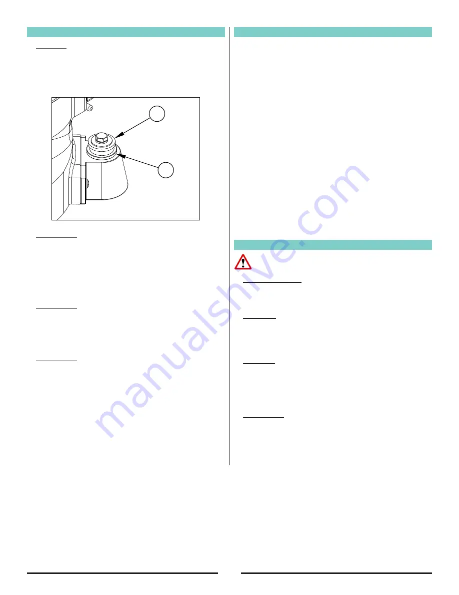
background image

12

A

B

Adjustment Procedures

Leveling

To level machine: Grasp caster adjusting screw “A” 

with an appropriate tool (pliers etc.).  Using a similar 

tool, loosen locknut “B” with a counter clockwise 

motion.  (Figure 6).

Condition 1

: Pad creates ridges on both edges or a 

“hop” is experienced.

Rotate both adjusting screws equal amounts 

clockwise.  Tighten locknut’s and test on a piece 

of plywood.  Repeat procedure until condition is 

corrected.  We recommend you not exceed 1/8” 

rotation for each attempt.

Condition 2

: Pad creates a ridge on the tip of the pad.

Rotate both adjusting screws counter clockwise,  

tighten locknut’s and test.  Repeat procedure until 

condition is corrected.  Use only 1/8 rotation for each 

attempt.

Condition 3

: Pad creates a ridge on only one side of the 

pad.

Either rotate the adjusting screw of the side effected 

clockwise or rotate the adjusting screw opposite 

counterclockwise, depending on whether the ridge 

terminates beyond the tip of the pad or prior to it.  If it 

is prior to the tip, adjust the side effected, otherwise 

adjust the opposite side.

Sanding Cuts & Sandpaper

Initial Cut

:

The purpose of the initial cut is to remove old finish and 

gross imperfections on the floor surface. Use a course 

(20-36 grit) grain abrasive.

If glazing, loading, or burning takes place 

immediately into an initial cut, select a coarser 

abrasive.  If this should occur during an initial cut, the 

abrasive has dulled and must be replaced.

Final Cuts

:

The purpose of a finishing cut is to remove the 

scratches produced during the initial cut. Use a fine (60-

80 grit) grain abrasive.
If the surface remains rough after a finishing cut, it may 

be necessary to use an even finer grain of abrasive (80-

100grit). Care should be taken in selecting the grit size 

of the abrasive. A very fine grain will close the pores 

on a wood floor making admission of a stain difficult. If 

glazing or burning should occur the abrasive has dulled 
and must be replaced.

Routine Maintenance

CAUTION

:  Failure to perform maintenance at 

recommended intervals may void warranty.

Carbon Brushes

Have the carbon brushes replaced at least every 500 

hours and more frequently under heavy use.

Dust Bag

Periodically the dust bag should be turned inside out, 

shaken vigorously and machine washed in cold water 

to prevent pore blockage and loss of dust control.

Bearings

To insure reliable performance, have armature and 

pad driver bearings inspected for wear or damage 

after every 1500 hours.  If used heavily, have the 

bearings replaced seasonally.

Lubrication

The machine comes fully lubricated.  The gears in the 

gear box have enough lubrication for approximately 

six months of normal operation.  Have the lubricant 

changed at least every 6 months or more frequently 

under heavy use.

Figure 6

Summary of Contents for American Sanders Super 7R 240V

Page 1: ...Edger Super 7R 240V Operator s Manual...

Page 2: ......

Page 3: ...s cannot read this manual have it explained fully before attempting to operate this machine All directions given in this book are as seen from the operator s position at the rear of the machine This...

Page 4: ...ile connected to a power source WARNING Injury can occur if protective clothing or equipment is not used while sanding Always wear safety goggles protective clothing and dust mask while sanding WARNIN...

Page 5: ...ools with your finger on the switch or energizing power tools that have the switch on invites accidents d Remove any adjustment wrench or key before turning the power tool on A wrench or key left atta...

Page 6: ...eld safety goggles or safety glasses As appropriate wear dust mask hearing protectors gloves and workshop apron capable of stopping flying debris generated by various operations The eye protection mus...

Page 7: ...e to the wheel s movement at the point of the snagging 4 Use special care when working corners sharp edges etc Avoid bouncing and snagging the accessory Corners sharp edges or bouncing have a tendency...

Page 8: ...8 Machine Components 1 2 3 4 5 6 7 Component 1 Control Switch 2 Dust Collection Bag 3 Operating Handles 4 Abrasive Wrench 5 Sanding Pad 6 Wall Guard 7 Caster Adjustment Screw...

Page 9: ...a nominal 230 volt circuit and has a grounding plug that resembles the plug illustrated as A in the sketch Make sure that the machine is connected to an outlet having the same configuration as the plu...

Page 10: ...he Dust Bag To prepare the machine for use with the included dust bag Part No 53544B follow this procedure 1 Install the dust bag by pressing the end onto the exhaust tube until the ring locks into th...

Page 11: ...nect the supply cable to the motor pigtail Figure 5 3 With the machine in the reclined position firmly grasp both handles and flip the control switch to the ON position Figure 4 4 Gradually lower pad...

Page 12: ...place immediately into an initial cut select a coarser abrasive If this should occur during an initial cut the abrasive has dulled and must be replaced Final Cuts The purpose of a finishing cut is to...

Page 13: ...ny pinch site Gearbox Lubricant To change the lubricant in the gearbox follow this procedure 1 Put the machine upside down on a bench 2 Align one of the two holes in the rubber pad with one of the thr...

Page 14: ...________________________________________________ ________________________________________________ ________________________________________________ ________________________________________________ ___...

Page 15: ...Electrical Schematic 15...

Page 16: ...16 Lower Assembly RF062000 070116 24 27 34 29 32 40 34 30 9 10 13 11 8 12 19 17 18 16 15 33 17 20 22 21 23 1 2 35 3 36 25 35 31 26 4 38 28 5 37 6 7 14 39...

Page 17: ...L YOKE ASM 2 Item Ref No Description Qty 21 316804 PLUG PIPE 1 22 56380216 DECAL CAUTION 1 23 56380639 DECAL PROP 65 1 24 53544B BAG DUST 1 25 303502 GEAR DRIVE 1 26 302306 COVER HOUSING ASM 1 27 3056...

Page 18: ...RF062100 072018 18 39 12 26 20 14 13 29 12 27 33 37 35 36 28 31 6 9 10 5 21 4 32 11 17 1 3 2 16 23 15 34 1 22 30 25 38 UPPER ASSEMBLY FOR 07098A 24 19 8 7 40 Upper Assembly 07098A 18...

Page 19: ...TE AMERICAN SANDERS 3 1 19 304204 HOUSING GEAR 1 Item Ref No Description Qty 20 962404 SCREW 10 24 X 3 1 4 FH ST PH 4 21 AS013500 FIELD COIL SUPER 7R ASM 240V 1 22 293514 PINION ARMETURE 1 23 308202 S...

Page 20: ...20 Upper Assembly 07099A RF067300 040417 UPPER ASSEMBLY FOR 07099A 17 12 33 36 22 18 27 12 32 29 21 20 14 13 18 28 31 6 9 10 8 7 23 4 26 30 35 11 3 1 2 16 25 24 1 15 34 5 19...

Page 21: ...1 407302 RING RETAINING 16 1 297604 OIL SEAL 92 17 1 AS014300 NAMEPLATE AMERICAN SANDERS 3 18 2 306802 PLUG VENT 19 1 304204 HOUSING GEAR 20 4 962404 SCREW 10 24 X 3 1 4 FH ST PH 21 1 47394A SWITCH D...

Page 22: ......

Page 23: ...ce Department for further assistance INSTRUCTIONS AND CONDITIONS FOR WARRANTY REIMBURSEMENT l Order replacement part Orders will be processed and charged as normal procedure l Call American Sanders fo...

Page 24: ...n AMANO Company 1 Eclipse Rd l PO Box 909 Sparta North Carolina 28675 l USA www pioneereclipse com www americansanders com 1 336 372 8080 1 800 367 3550 Fax 1 336 372 2913 2017 American Sanders LT0745...

Reviews:

Related manuals for American Sanders Super 7R 240V